
Output terminal and current transformer

An output terminal and converter technology, which is applied in the output power conversion device, the conversion of AC power input to DC power output, and the structural parts of the conversion equipment, etc. Cumbersome and other problems, to achieve the effect of reducing installation space requirements and facilitating installation and maintenance

Pending Publication Date: 2019-03-29
江苏经纬轨道交通设备有限公司
View PDF0 Cites 0 Cited by
  • Summary
  • Abstract
  • Description
  • Claims
  • Application Information

AI Technical Summary

Problems solved by technology

[0007] The embodiments of the present invention aim at the fact that when the cable output is directly used in the above-mentioned converter, the busbar body bears a large stress, which is likely to cause uneven current distribution, and the inspection efficiency is low when the transfer copper bar is combined with the cable output, To solve the problem of cumbersome operation, an output terminal and converter are provided

Method used


Image

  • Output terminal and current transformer
  • Output terminal and current transformer
  • Output terminal and current transformer

Examples


Embodiment Construction

[0025] In order to make the object, technical solution and advantages of the present invention clearer, the present invention will be further described in detail below in conjunction with the accompanying drawings and embodiments. It should be understood that the specific embodiments described here are only used to explain the present invention, not to limit the present invention.

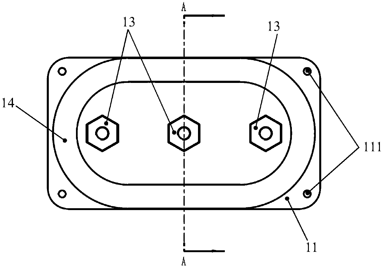
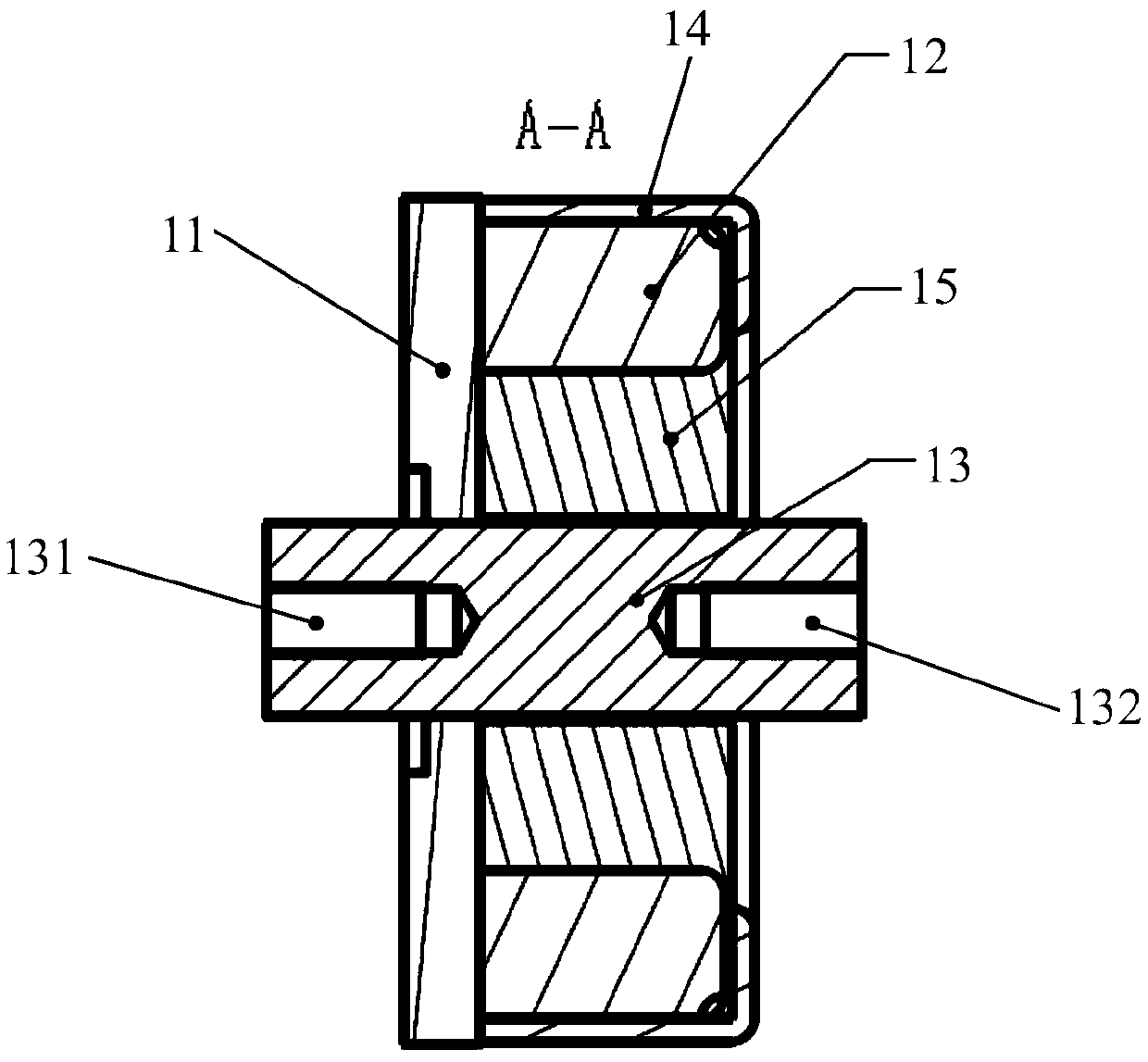
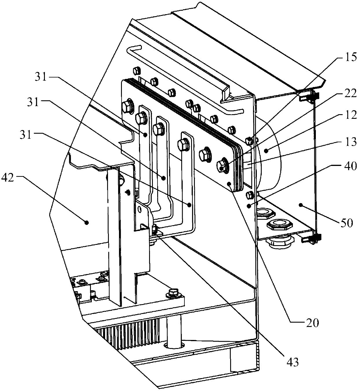
[0026] Such as Figure 1-2 As shown, it is a schematic structural diagram of an output terminal provided by an embodiment of the present invention, and the output terminal can be applied to power output of power electronic equipment such as a converter. The output terminal in this embodiment includes a backplane 11, a magnetic ring 12, and a plurality of binding posts 13 (the number of binding posts 13 can be adjusted according to the application scene of the output terminal, for example, when the output terminal is used to output three-phase electric energy, the output The terminal may comprise t...


PUM


Abstract

The embodiment of the present invention provides an output terminal and a current transformer. The output terminal includes a backplane, a magnetic ring, and a plurality of binding posts, wherein theplurality of binding posts pass through the backplane and are fixedly connected to the backplane; the plurality of binding posts are insulated from each other; the first end of each binding post is located on the first side of the backplane; the second end of each binding post is located on the second side of the backplane; the magnetic ring is fixedly connected to the backplane to surround the plurality of binding posts; and the magnetic ring protruding from the second side of the backplane has a smaller size than the second end of each binding post protruding from the second side of the backplane. In the embodiment of the invention, the binding posts and the magnetic ring are integrated into the backplane, and the output terminal can be waterproof and dustproof without a cable gland. Wiring points can be checked without disassembling a current transformer box, which facilitates the installation and maintenance of the output terminal, eliminates the need for separately installing themagnetic ring, and reduces the need for installation space.

Description

technical field [0001] The invention relates to the field of power electronic equipment, and more specifically, to an output terminal and a converter. Background technique [0002] As a power conversion device, the converter has been widely used in power electronic equipment. The final output of the converter is alternating current or direct current, and currently the converter usually uses a transfer copper bar or directly uses a cable crimped with a connecting terminal (such as an OT terminal) to output electric power. [0003] When two or more outputs are required, the converter outputs electric energy by opening holes in the transfer copper bar or directly setting multiple openings on the busbar body, and using multiple cables. In this two-way or multi-way output structure, the busbar body or the transfer copper bar is fixed on the box body or other structural parts through insulating parts, and the cables are directly tied with cable ties inside the box body. [0004]...

Claims


Application Information

Patent Timeline
IPC IPC(8): H02M7/00
CPCH02M7/003
Inventor 秦井武李亮郝玉飞朱程晟王禹严政
Owner 江苏经纬轨道交通设备有限公司
Learn More