
Device and system for DC energy consumption, and control method

A technology of energy-consuming devices and energy-dissipating resistors, applied in information technology support systems, power network operating system integration, power transmission AC networks, etc., can solve problems such as difficult value selection of resistors, high cost performance, uneven breaking voltage, etc., and achieve risk Small size, simple method, avoid the effect of voltage unevenness

Active Publication Date: 2019-03-29
詹长江
View PDF2 Cites 5 Cited by
  • Summary
  • Abstract
  • Description
  • Claims
  • Application Information

AI Technical Summary

Problems solved by technology

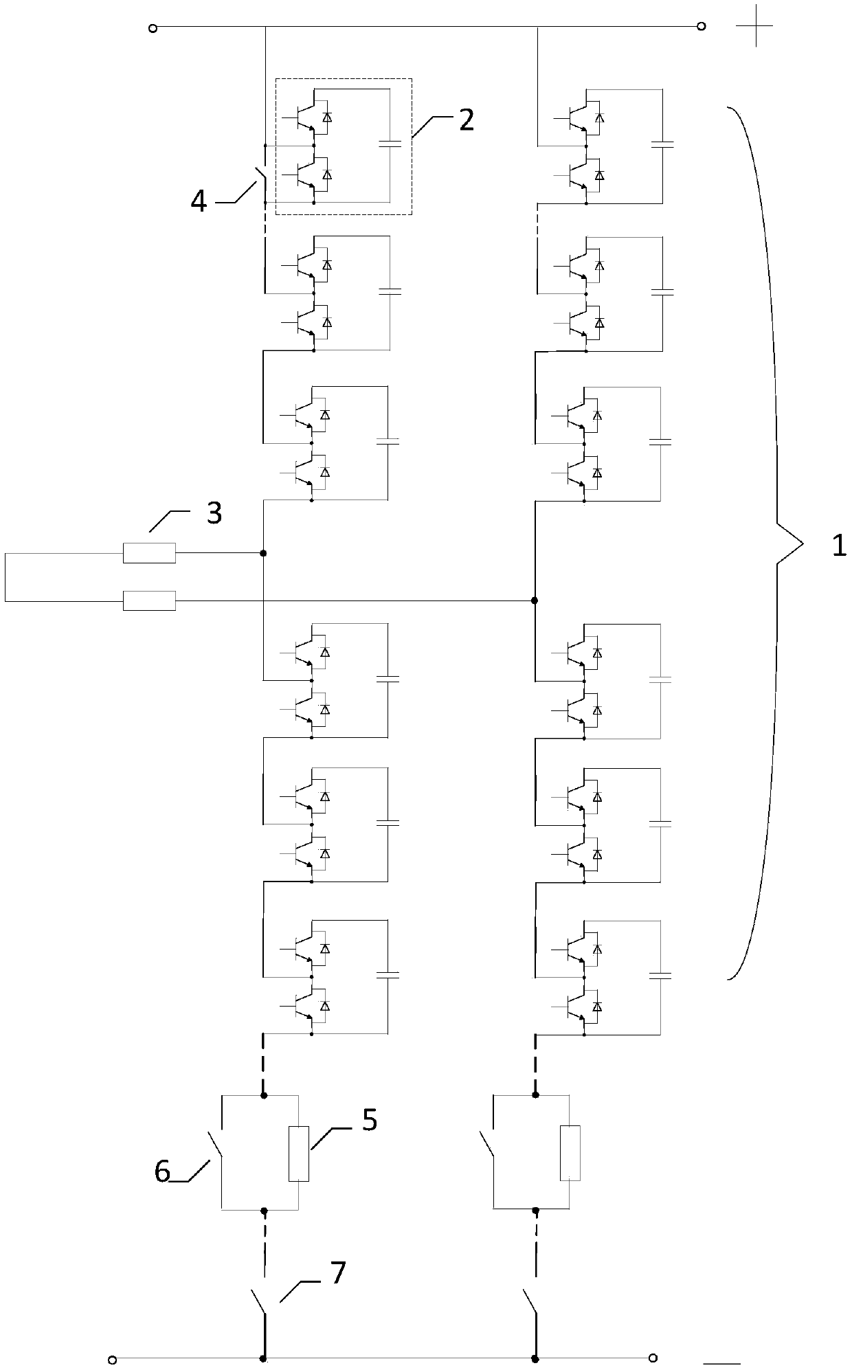
[0004] In order to solve the above problems, the present invention proposes a DC energy-consuming device and a control method using the above-mentioned device. The device is connected in parallel between the positive and negative poles of the medium and high-voltage DC lines, and the control of the input and exit of the energy-consuming sub-modules can be adjusted. The current flowing through the energy-dissipating resistor controls the energy-dissipating speed. The device is cost-effective and solves the problems of uneven breaking voltage and difficult value selection of resistors in the prior art.

Method used


Image

  • Device and system for DC energy consumption, and control method
  • Device and system for DC energy consumption, and control method
  • Device and system for DC energy consumption, and control method

Examples


Embodiment Construction

[0044] The present invention will be further described below in conjunction with accompanying drawing.

[0045] In order to achieve the above object, the concrete scheme that the present invention adopts is as follows:

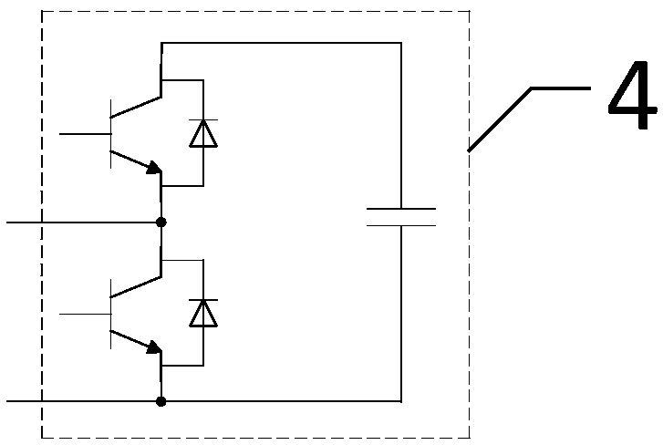
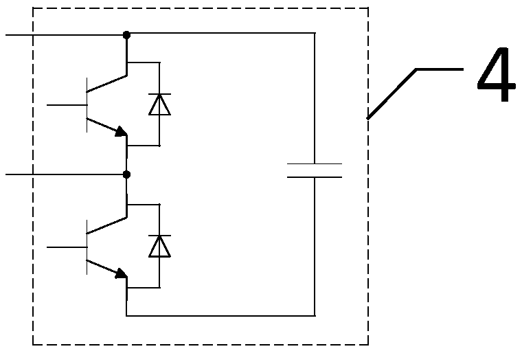
[0046] Such as figure 1 As shown, a DC energy consumption device 1, the device is composed of an energy consumption branch and an energy consumption resistor 3, the energy consumption branch is composed of at least one energy consumption sub-module 2 connected in series in the same direction, the series connection The head end is defined as the positive pole of the device, and the tail end of the series connection is defined as the negative pole of the device; the positive pole of the device is connected to the positive pole of the DC line, and the negative pole of the device is connected to the negative pole of the DC line; one end of the energy dissipation resistor is connected to the The connection point between any two energy-consuming sub-modules in the ...


PUM


Abstract

The invention discloses a device for DC energy consumption. The device is composed of an energy consuming branch and a power consuming resistor. The energy consuming branch is formed by connecting atleast one energy consuming sub-module in series in the same direction. A head end of the series connection is defined as a positive pole of the device, and a tail end of the series connection is defined as a negative pole of the device. The positive pole of the device is connected with the positive pole of a direct current line, and the negative pole of the device is connected with the negative pole of the direct current line. One end of the power consuming resistor is connected with a junction point between the two energy consuming sub-modules in the energy consuming branch, and the other endis used as an output end of the device. The device also includes a system for DC energy consumption, and the system is formed by the device for DC energy consumption, and a control method. When DC line voltage is increased, through adjusting input or exist number of the energy consuming sub-modules in the energy consuming branch, current flowing through the energy consuming resistor is controlled, thereby controlling energy consumption speed. The device has high cost performance, high reliability, and is easy to implement.

Description

technical field [0001] The invention belongs to the technical field of high-power electric current conversion, and in particular relates to a DC energy consumption device, system and control method. Background technique [0002] In HVDC power transmission system, DC energy consumption device is a crucial equipment. The DC energy consumption device is mainly used in the application scenario of island power supply. If the power generation end is an inertial power source similar to wind power, when the power receiving end fails, because the power cannot be sent out, the energy will be accumulated on the DC side, resulting in the voltage of the DC transmission line. If it rises, it will endanger the safe operation of the equipment. [0003] In the prior art, the method adopted is that when the DC voltage is too high, through the control of the power electronic device, a resistor is put in, and the input of the resistor will cause the DC voltage to drop. When the energy consumpt...

Claims


Application Information

Patent Timeline
Patent Type & Authority Applications(China)
IPC IPC(8): H02J3/36H02J3/14
CPCH02J3/14H02J3/36Y04S20/222Y02E60/60Y02B70/3225
Inventor 詹长江谢晔源李钢王宇
Owner 詹长江
Learn More