A precision machining process for stamping process of thin film parts

A precision machining and parts technology, applied in the field of precision parts technology manufacturing, can solve problems such as the inability to accurately determine the mold distance, and achieve the effect of being conducive to mass production and easy to realize

Active Publication Date: 2021-08-06
陈志刚
View PDF0 Cites 0 Cited by
  • Summary
  • Abstract
  • Description
  • Claims
  • Application Information

AI Technical Summary

Problems solved by technology

However, when using the screw to shake the distance between the molds, or using spacers to adjust the distance, it can only be adjusted by visual inspection or experience, and the distance between the molds cannot be accurately determined. In actual use, repeated adjustments may be required to meet the standard

Method used


Image

  • A precision machining process for stamping process of thin film parts
  • A precision machining process for stamping process of thin film parts

Examples


Embodiment 1

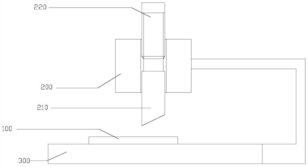
[0021] refer to figure 1 As shown, a precision machining process of a film part stamping process is performed on a film part 100 for stamping and cutting, including the following steps:

[0022] (1) The stamping assembly is fixed on the stroke module 200 , and the stamping assembly is placed in the stroke module 200 and screwed to the stroke module 200 . The stamping assembly includes a stamping upper die 210, an adjustment ruler 220 fixedly connected to the stamping upper die 210;

[0023] (2) Debug stamping: start the stroke module 200 to carry out a stamping, when the stroke module moves downward, rotate the adjustment ruler 220 to make the stamping upper die 210 and the stamping lower die 200 contact each other, record the adjustment ruler 220 and the stroke The upper surface of the module 200 is flush with the scale; start the stroke module 200 to reset, and then according to the thickness d of the thin film part 100 to be processed, the rotation adjustment ruler 210 mov...

Embodiment 2

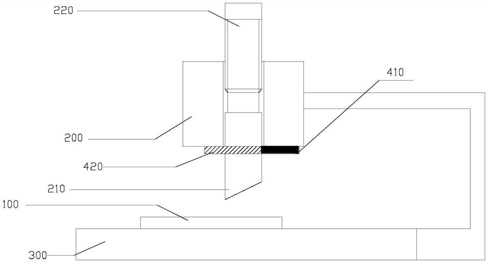
[0030] refer to figure 2 As shown, a precision machining process of a film part stamping process is performed on a film part 100 for stamping and cutting, including the following steps:

[0031] (1) The stamping assembly is fixed on the stroke module 200 , and the stamping assembly is placed in the stroke module 200 and screwed to the stroke module 200 . The stamping assembly includes a stamping upper die 210 and an adjustment ruler 220 fixedly connected to the stamping upper die 210 . A connection fixture is fixed below the stroke module 200 , the fixture includes a fixedly connected base 410 and an elastic clip 420 , and the base 410 is fixed below the stroke module 200 .

[0032] (2) Debug stamping: start the stroke module 200 to perform a stamping, when the stroke module moves downward, open the elastic jaw 420, rotate the adjustment ruler 220 to make the stamping upper die 210 and the stamping lower die 200 touch each other , then reset the elastic jaw 420, record the ...


PUM

PropertyMeasurementUnit
thicknessaaaaaaaaaa
thicknessaaaaaaaaaa

Abstract

The invention relates to a precision machining process of a film part stamping process, comprising the following steps: (1) fixing a stamping assembly in a stroke module through a threaded connection, the stamping assembly includes a stamping upper die, and is fixedly connected to the stamping upper die Adjusting ruler on the top; (2) debugging stamping: start the stroke module to carry out a stamping, when the stroke module moves downward, rotate the adjusting ruler to make the stamping upper die and the stamping lower die contact each other, and record the adjustment ruler and the stroke The scale on the upper surface of the module is flush; start the reset of the stroke module, and then according to the thickness d of the film part to be processed, the rotation adjustment ruler moves down relative to the stroke module by h, h=d; (3) Place the film part to be processed on the stamping lower die , start the stroke module for stamping. The process provided by the invention can avoid "wrinkling" of parts caused by excessive stamping depth, which will damage the surface smoothness of film parts; and avoid damage to mold equipment caused by too deep cutting of blades.

Description

technical field [0001] The invention belongs to the field of production and manufacture of precision parts technology, and in particular relates to a precision processing technology of a stamping technology of film parts. Background technique [0002] The stamping process in the prior art generally adopts program control, and the parts to be cut are placed on the processing bed, and then the stamping process is performed using a program-controlled blade. Doing so can be applied to mass production processes. However, the processing requirements of some precision parts are very strict, especially the cutting process of some film parts, which requires precise adjustment of the mold to control the punching depth of the blade. However, for most stamping processes, the method of changing the program to control the depth of stamping is very cumbersome, which is not conducive to the needs of actual production. Moreover, due to the limitation of the production method, the adjustmen...

Claims


Application Information

Patent Timeline
Patent Type & Authority Patents(China)
IPC IPC(8): B21D28/14B21D28/04
CPCB21D28/04B21D28/14
Inventor 陈志刚
Owner 陈志刚
Why Eureka
Try Eureka