
Electric meter coupling antenna

A technology for coupling antennas and ammeters, applied to antennas, antenna parts, antenna supports/installation devices, etc., can solve the problem of damaging the structure of the ammeter shell and achieve the effect of antenna feeding

Pending Publication Date: 2019-03-26
杭州易和互联软件技术有限公司
View PDF3 Cites 3 Cited by
  • Summary
  • Abstract
  • Description
  • Claims
  • Application Information

AI Technical Summary

Problems solved by technology

[0005] At present, the existing VHF meter antennas are all in the form of wired feeding, that is, the antenna must be connected to the internal module through a cable, and connecting the antenna outside the meter casing will destroy the original casing structure of the meter

Method used


Image

  • Electric meter coupling antenna
  • Electric meter coupling antenna

Examples


Embodiment 1

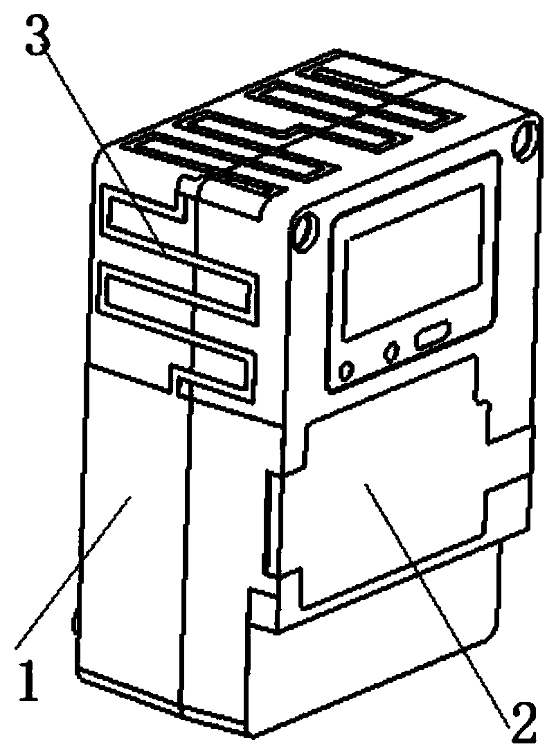
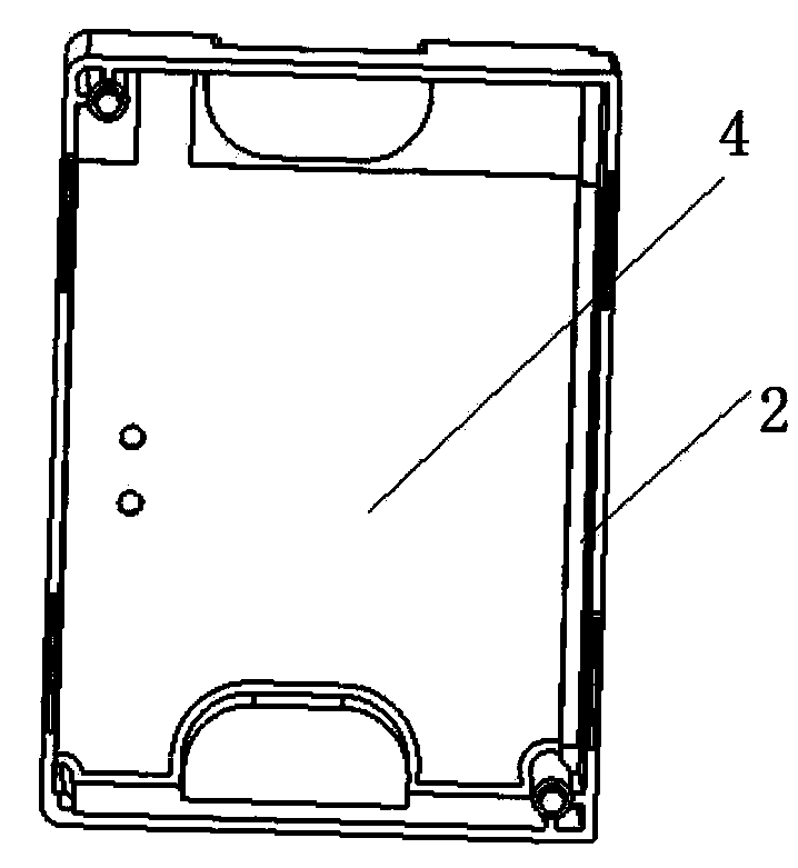
[0019] Such as figure 1 , 2 As shown, the present invention is a coupling antenna for electric meters, which includes an external antenna 1 arranged on the outer box body 1 of the electric meter and a receiving antenna composed of an internal antenna arranged in the internal module of the inner box body 2 of the electric meter, and the external antenna is sprayed The bending circuit 3 is composed of the metal layer on the side of the outer box of the electric meter, and the internal antenna is the radiation sheet 4 in the inner box of the electric meter. The bending circuit is arranged on two or three sides of the outer box body of the electric meter.

Embodiment 2

[0021] The electric meter coupling antenna of this embodiment includes an external antenna arranged on the electric meter outer box and a receiving antenna composed of an internal antenna arranged in the inner module of the electric meter inner box, and is pasted on the side of the electric meter outer box by a coupling sheet. A bending circuit composed of sheet metal sheets, and the internal antenna is a radiation sheet in the inner box of the electric meter. The bending circuit is arranged on two or three sides of the outer box body of the electric meter.

[0022] The advantages of the present invention are:

[0023] 1. The coupling antenna is divided into internal and external parts. The external antenna is close to the side of the outer box of the meter, and the internal antenna is close to the surface of the internal module of the internal box. The external antenna and the internal antenna are separated by a certain distance. The internal module excites the internal ante...


PUM


Abstract

The invention discloses an electric meter coupling antenna, which comprises a receiving antenna formed by an external antenna arranged on an outer electric meter case body and an internal antennas arranged in an internal module of an inner electric meter case body. The receiving antenna forms an LC loop by tuning inductance and feeding connection. The external antenna is a bending circuit arrangedat the side of the outer electric meter case body; and the internal antenna includes a radiation sheet body arranged in the inner electric meter case body. The electric meter coupling antenna has aninternal part and an external part; the external antenna is in close contact with the side of the outer electric meter case body; the internal antenna is in close contact with the surface of the internal module of the inner case body; and the external antenna and the internal antenna are spaced at a certain distance. The internal antenna is excited by the internal module to generate surface currents and a corresponding structure is designed at the meter case to meet the spatial impedance matching condition, so that the excited currents generated by the internal module generate induced currentsat the surface of the external antenna to realize spatial feeding. The antenna is combination of the internal part and the external part.

Description

technical field [0001] The invention relates to the technical field of antennas, in particular to an electric meter coupling antenna. Background technique [0002] Driven by the awareness of green energy conservation, the smart grid with smart meters as the core has become a key area of ​​development in countries all over the world. The development of smart grids can also benefit utilities and consumers. For example, the smart grid can help power organizations reduce operating expenses, reduce power theft, optimize operations, and respond to user needs in real time. Users also have the opportunity to enjoy more flexible pricing, save costs due to network metering and help realize home automation. Therefore, the development prospect of the smart grid is quite promising. Global shipments of smart meters are expected to grow from just a few million units in 2008 to approximately 50 million units in 2014, a compound annual growth rate (CAGR) of 48%. [0003] From the perspec...

Claims


Application Information

Patent Timeline
Patent Type & Authority Applications(China)
IPC IPC(8): H01Q1/22H01Q1/36H01Q1/38H01Q1/50
CPCH01Q1/225H01Q1/36H01Q1/38H01Q1/50
Inventor 姚近蔡元铭王韬樾
Owner 杭州易和互联软件技术有限公司
Learn More