Control circuit for weighing sensor
A technology of weighing sensor and control circuit, applied in the direction of logic circuit interface device, detailed information of weighing equipment, logic circuit connection/interface layout, etc. Changes and other issues to achieve the effect of simple structure, flexible selection, and flexible matching
- Summary
- Abstract
- Description
- Claims
- Application Information
AI Technical Summary
Problems solved by technology
Method used
Image
Examples
Embodiment 1
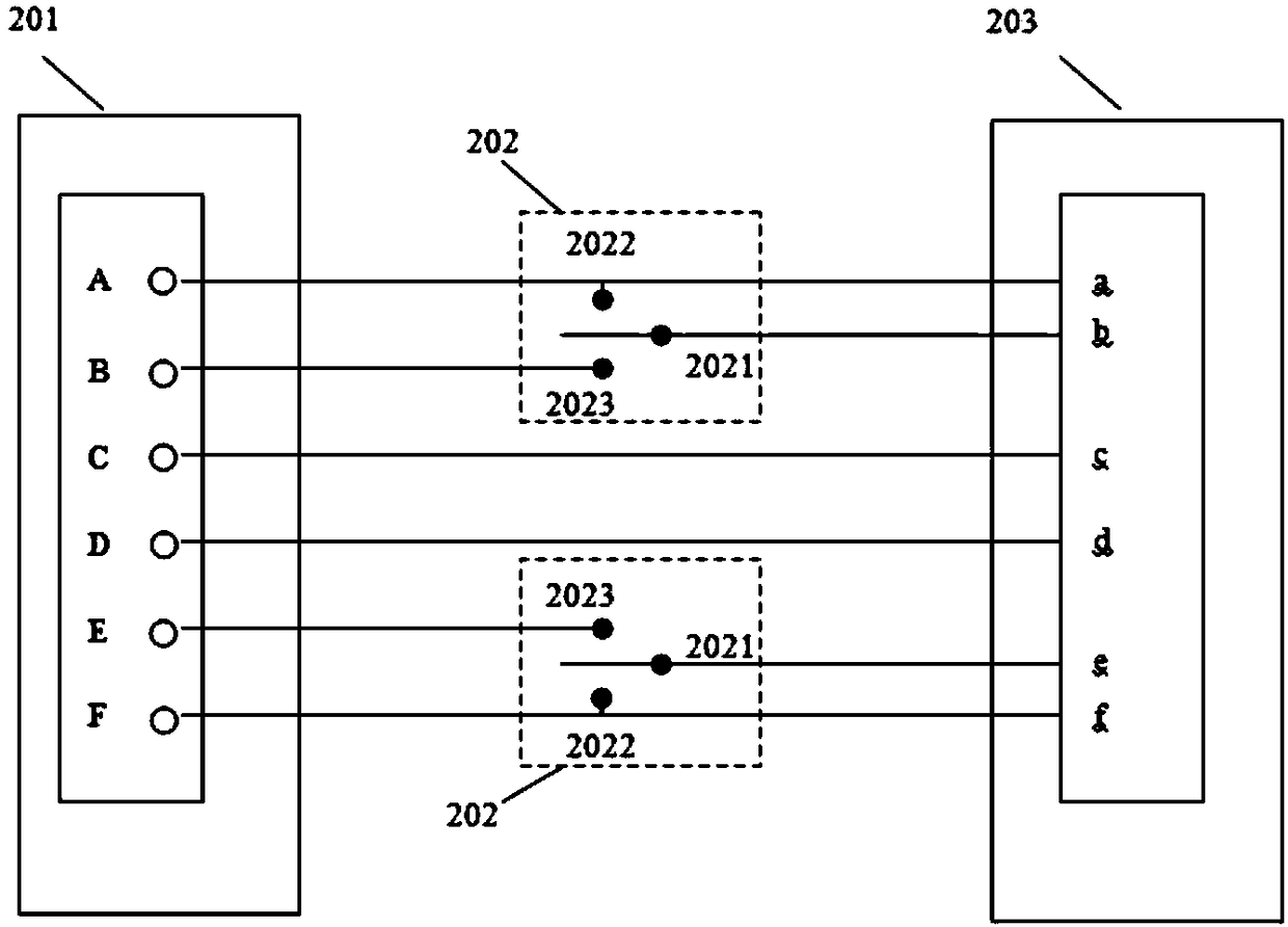
[0034] figure 2 It shows the connection structure diagram of the load cell and the six-wire signal processing equipment of the present invention.
[0035] like figure 2 As shown, the connector 201 includes six terminals A~F and the six interfaces a~f of the signal processing device 203 respectively correspond to excitation (+), feedback (+), output (+), output (-), excitation ( -) and feedback (-), terminals C and D are directly connected to interfaces c and d of the signal processing device 203 respectively, and an analog switch 202 is respectively set between terminals A and B, and between terminals E and F. When the signal processing device 203 is a six-wire system, the analog switch 202 is set so that the terminals A, B, E, and F are respectively connected to the interfaces a, b, e and f of the signal processing device 203; when the signal processing device 203 is a four-wire system , the analog switch 202 disconnects the terminals B and E, and only the terminals A and...
Embodiment 2
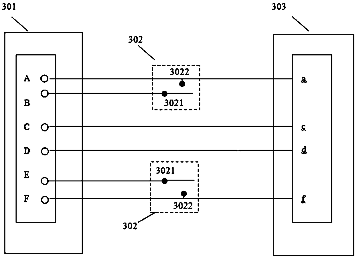
[0041] image 3 A connection structure diagram of the load cell and the four-wire signal processing device 303 of the present invention is shown.
[0042] like image 3As shown, the connector 301 includes six terminals A~F corresponding to excitation (+), feedback (+), output (+), output (-), excitation (-) and feedback (-), and the signal processing device 303 includes The four interfaces a, c, d and f correspond to excitation (+), output (+), output (-) and excitation (-) respectively, and terminals C and D are directly connected to interfaces c and d of the signal processing device 303 respectively. An analog switch 302 is provided between terminals A and B, and between terminals E and F, respectively. When the signal processing device 303 is a four-wire system, set the analog switch 302 so that terminals A and B are short-circuited, and terminals E and F are short-circuited, and then respectively connected to interfaces a and f of the signal processing device 303 .
[0...
PUM
 Abstract
Description
Claims
Application Information
 - R&D
- Intellectual Property
- Life Sciences
- Materials
- Tech Scout
- Unparalleled Data Quality
- Higher Quality Content
- 60% Fewer Hallucinations
Browse by: Latest US Patents, China's latest patents, Technical Efficacy Thesaurus, Application Domain, Technology Topic, Popular Technical Reports.
© 2025 PatSnap. All rights reserved.Legal|Privacy policy|Modern Slavery Act Transparency Statement|Sitemap|About US| Contact US: help@patsnap.com


