
Small punch creep test device and method with capability to precise and continuous loading

A technology of creep test and small punch, which is applied in the direction of measuring device, applying stable tension/pressure to test material strength, instruments, etc. It can solve the problem of applying tangential force on the test surface, high test device, discontinuous applied load, etc. problem, to achieve the effect of simplifying the process of changing the sample, avoiding tilting or jamming, and avoiding uneven clamping force

Active Publication Date: 2019-03-22
XI AN JIAOTONG UNIV
View PDF4 Cites 3 Cited by
  • Summary
  • Abstract
  • Description
  • Claims
  • Application Information

AI Technical Summary

Problems solved by technology

[0006] (2) Static load loading (such as weights) is used, limited by the limitations of weight specifications, the applied load is discontinuous, and when the top loading method is adopted, the test device is usually high and the working intensity is high
[0007] (3) The punch rod is long, and the problem of tilting or jamming may occur during loading, which will affect the measurement accuracy of material properties
[0008] (4) The upper and lower fixtures of the sample are generally fastened by four screws. The different tightening degrees of the screws will induce assembly stress, resulting in uneven stress on the sample, and may even apply a tangential force to the test surface and damage the sample. , affecting the characterization of material properties

Method used

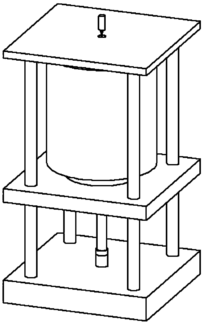

Image

  • Small punch creep test device and method with capability to precise and continuous loading
  • Small punch creep test device and method with capability to precise and continuous loading
  • Small punch creep test device and method with capability to precise and continuous loading

Examples


Embodiment Construction

[0040] In order to enable those skilled in the art to better understand the solutions of the present invention, the following will clearly and completely describe the technical solutions in the embodiments of the present invention in conjunction with the drawings in the embodiments of the present invention. Obviously, the described embodiments are only It is an embodiment of a part of the present invention, but not all embodiments. Based on the embodiments of the present invention, all other embodiments obtained by persons of ordinary skill in the art without making creative efforts shall fall within the protection scope of the present invention.

[0041] It should be noted that the terms "first" and "second" in the description and claims of the present invention and the above drawings are used to distinguish similar objects, but not necessarily used to describe a specific sequence or sequence. It is to be understood that the data so used are interchangeable under appropriate ...


PUM


Abstract

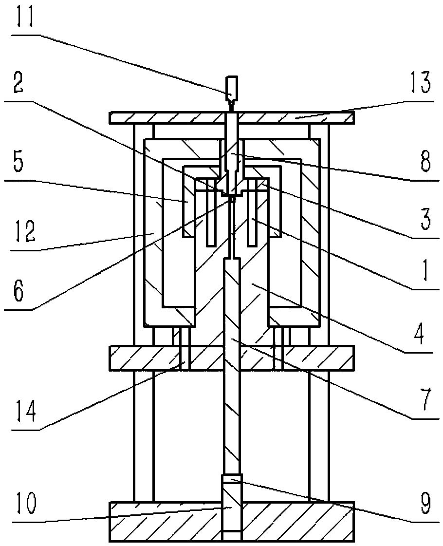
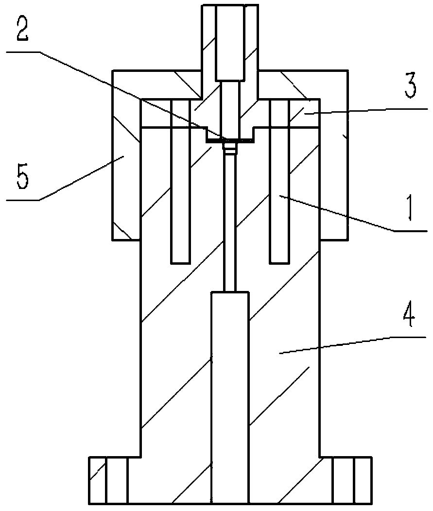
The invention discloses a small punch creep testing device and method with capability to precise and continuous loading. The testing device comprises an upper clamp, a lower clamp, a clamping sleeve,a positioning pin, a specimen, a punch head, a punch, a measuring rod, a load sensor, a hydraulic jack, a linear variable differential transformer, a heating furnace and a bracket. The testing methodcomprises the following steps of installing the specimen, debugging and centering, applying the temperature, applying the load, collecting the data and the like. The testing device and the testing method have the advantages that the bottom end loading type is adopted, the static load is replaced with the hydraulic jack, the load can be continuously and stably applied, and the loading accuracy is improved; by arranging the step-shaped punch and the measuring rod, the tilting or seizure of the rod can be effectively avoided; by replacing the group bolt tightening with the thread connection to, the influence by assembly stress is greatly eliminated; by arranging a positioning pin, the centering property is better.

Description

【Technical field】 [0001] The invention relates to the technical field of small-punch creep testing, in particular to a small-punch creep testing device and method capable of realizing precise and continuous loading. 【Background technique】 [0002] Many devices in energy, petrochemical, aerospace and other fields work under high temperature conditions, which puts forward high requirements on the safety of components. The damage of materials at high temperatures is the main factor that threatens the reliable operation of modern high temperature devices. Equipment that operates at high temperatures for a long time is prone to material deterioration and failure, and the main failure mode is creep. Scholars at home and abroad have proposed many methods in the evaluation of material properties of high-temperature components, which can be roughly divided into non-destructive testing (metal structure testing, hardness testing, ultrasonic testing, numerical simulation, etc.) and dest...

Claims


Application Information

Patent Timeline
IPC IPC(8): G01N3/18G01N3/02
CPCG01N3/02G01N3/18G01N2203/0003G01N2203/0019G01N2203/0048G01N2203/0071G01N2203/0226
Inventor 朱林波盛晓茜洪军张早校陈剑张培源
Owner XI AN JIAOTONG UNIV
Learn More