


Quick Research
Generate reliable direction feasibility study reports for your R&D in just a few steps.

Technical Q&A
Discover and master advanced knowledge NOW. Basics, ideas, possibilities, all at once.

Find Solutions
As an expert in R&D theories, this can generate solutions to your technical problems instantly.

Evaluate Feasibility
Analyze your overall solution with one click, know your potential R&D risks in advance.

Monitor Landscape
Get weekly tech updates, stay abreast of the latest tech innovations and key insights.
Device for cleaning away canal water distributing opening floating objects
A technology for cleaning devices and floating objects, which can be used in water conservancy projects, artificial waterways, buildings, etc., and can solve the problems of inconvenience and danger of manual cleaning.
- Summary
- Abstract
- Description
- Claims
- Application Information
AI Technical Summary
Benefits of technology
Problems solved by technology
Method used
Image

Examples
Embodiment 1
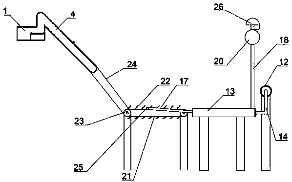
[0029] Refer to attached Figures 1 to 8 : the device for clearing floating objects at water channel diversions in the figure includes a garbage collection tank 1, which floats on the water surface, and the both sides of its end facing the water flow are provided with installation plates 4 inclined to extend into the water. The plate 4 preferably extends 2.5 meters underwater at an angle of 45 degrees. The lower part of the end of the garbage collection tank 1 facing the water flow is V-shaped to facilitate the passage of water, and the top of the garbage collection tank 1 is fixed with hanging lugs for connecting ropes, so as to facilitate the use of ropes to pull the garbage collection tank 1 to prevent it from floating with the water. Walk.
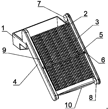
[0030] An interception net and a scraper transmission device for intercepting garbage are arranged between the installation plates on both sides of the garbage collection tank 1 .
[0031] The intercepting net is composed of several ...
Embodiment 2
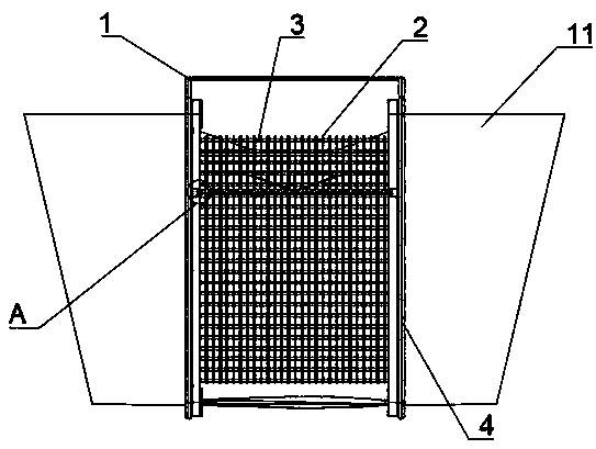
[0039] Refer to attached figure 2 and 3 , the main structure of the second embodiment is basically the same as that of the first embodiment, and the main difference is that the outer side of the mounting plate 4 is provided with a fence 11 for collecting garbage; in order to improve the overall buoyancy of the device of the present application, the fence 11 can be an air bag, and in order to facilitate Adjust the buoyancy according to the gravity of the garbage collection tank 1 and the interception net, the fence 11 can be spliced up and down by the air bag and the water bag, and the top of the fence 11 is fixedly connected with a rope, and the fence can be realized by connecting the rope to the fixed object on the bank. Rough positioning in water.
Embodiment 3
[0041] The main structure of the third embodiment is basically the same as that of the first embodiment, the main difference is that the garbage storage box with an upper opening is placed in the garbage collection tank 1, not shown, and the garbage that is entered into the garbage collection tank 1 by the scraper 5 directly falls into the garbage. In the collection box, to facilitate the follow-up garbage disposal; for the convenience of taking out the garbage storage box from the garbage collection tank 1, lifting lugs are fixed on the top of the garbage storage box.
PUM
 Abstract
Description
Claims
Application Information
 - R&D Engineer
- R&D Manager
- IP Professional
- Industry Leading Data Capabilities
- Powerful AI technology
- Patent DNA Extraction
Browse by: Latest US Patents, China's latest patents, Technical Efficacy Thesaurus, Application Domain, Technology Topic, Popular Technical Reports.
© 2024 PatSnap. All rights reserved.Legal|Privacy policy|Modern Slavery Act Transparency Statement|Sitemap|About US| Contact US: help@patsnap.com