Crystallization equipment special for remelting in-situ micro-alloying of high-speed steel electroslag and smelting method thereof

A technology of electroslag remelting and crystallization equipment, which is applied in the field of microalloying of high-speed steel, can solve problems such as uneven distribution along the radial direction and coarse carbide structure, and achieve carbide size reduction, fine structure, convenient and reliable operation Effect

Inactive Publication Date: 2019-03-19
HEBEI UNIV OF TECH
View PDF5 Cites 0 Cited by
  • Summary
  • Abstract
  • Description
  • Claims
  • Application Information

AI Technical Summary

Problems solved by technology

[0005] The technical problem to be solved by the present invention is to provide a special crystallization equipment for in-situ microalloying of high-speed steel, and a method for melting using the crystallizer. Uncontrollable range and other problems, in order to improve the problem of coarse carbide structure and uneven radial distribution in large-size high-speed steel

Method used


Image

  • Crystallization equipment special for remelting in-situ micro-alloying of high-speed steel electroslag and smelting method thereof
  • Crystallization equipment special for remelting in-situ micro-alloying of high-speed steel electroslag and smelting method thereof
  • Crystallization equipment special for remelting in-situ micro-alloying of high-speed steel electroslag and smelting method thereof

Examples


Embodiment 1

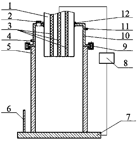
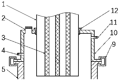
[0025] Such as Figure 1-Figure 4 As shown, the special crystallization equipment for in-situ microalloying of high-speed steel provided in this embodiment includes a bottom water tank 7, a transformer 8 and a crystallizer 5. The crystallizer 5 is located on the bottom water tank 7 and forms a crystallization pool together with the bottom water tank 7. An atmosphere cover 10 is arranged above the crystallization pool, and the atmosphere cover 10 is movably connected with the crystallizer 5 through buckles 9. The lower end of one side of the atmosphere cover 10 is provided with an air inlet 4, and the upper end of the side opposite to the air inlet 4 is provided with an air outlet 11. The top of the atmosphere cover 10 is provided with a slag filling port 2 near the edge, and the center of the atmosphere cover 10 is provided with a circular through hole, so that the electroslag remelted high-speed steel self-melting electrode steel ingot 1 can enter the crystallization pool thro...


PUM

PropertyMeasurementUnit
diameteraaaaaaaaaa
lengthaaaaaaaaaa

Abstract

The invention relates to the field of high-speed steel micro-alloying, in particular to crystallization equipment special for remelting in-situ micro-alloying of high-speed steel electroslag and a smelting method thereof. The crystallization equipment special for remelting in-situ micro-alloying of the high-speed steel electroslag comprises a bottom water tank, a transformer and crystallizers. A crystallizing pond is formed jointly by the crystallizers and the bottom water tank. An atmosphere cover is arranged on the crystallizing pond. Movable connection of the atmosphere cover and the crystallizers is achieved through connecting parts such as buckles and bolts. An air inlet is formed in the lower end of one side of the atmosphere cover, and an air outlet is formed in the upper end of theside, opposite to the air inlet, of the atmosphere cover. A slag-filling port is formed in the position, close to the edge, of the top of the atmosphere cover. A circular through hole is formed in the center of the atmosphere cover. One end of the transformer is connected with the bottom water tank, the other end of the transformer is connected with a self-fluxing electrode of the high-speed steel through a welded fake electrode, and a closed loop circuit is formed. By adopting the crystallization equipment for conducting of electroslag remelting, the yield is effectively improved for easy-to-burn microalloy elements; besides, elements added can participate in an organization evolution process as nucleation particles; texture of the high-speed steel is refined obviously; and the size of carbides is lowered conspicuously.

Description

technical field [0001] The invention relates to the field of micro-alloying of high-speed steel, in particular to a special crystallization equipment for in-situ micro-alloying of high-speed steel and a melting method thereof implemented by electroslag remelting technology. Background technique [0002] High-speed steel is used as the main basic material for manufacturing cutting tools because of its excellent strength and toughness, good wear resistance, red hardness and tool formability. The uniform and fine carbide structure in high-speed steel can greatly improve the performance of high-speed steel. The carbides in the center of the industrial-grade large-size high-speed steel ingot produced by conventional casting methods are coarse in size and extremely unevenly distributed in the radial direction, which seriously reduces the high-speed steel. steel properties. [0003] Microalloying treatment can increase the nucleation rate of the metal solidification process, the...

Claims


Application Information

Patent Timeline
Patent Type & Authority Applications(China)
IPC IPC(8): C22C33/04C22B9/187C22C38/22C22C38/24C22C38/02C22C38/04
CPCC22B9/18C22C33/04C22C38/005C22C38/02C22C38/04C22C38/22C22C38/24
Inventor 肖志霞梁玉殷福星冯建航
Owner HEBEI UNIV OF TECH
Why Eureka
Try Eureka