Al technical title is built by PatSnap Al team. It summarizes the technical point description of the patent document.
A technology of automatic feeding and trays, applied in the direction of conveyors, conveyor objects, conveyor control devices, etc., can solve the problems of conveyor belt motor damage, difficulty in ensuring directionality, long assembly time, etc., to improve accuracy and reduce The effect of manual labor intensity and small footprint
Pending Publication Date: 2019-03-19
XIAMEN BANGZHONG TECH
View PDF9 Cites 12 Cited by
Summary
Abstract
Description
Claims
Application Information
AI Technical Summary
This helps you quickly interpret patents by identifying the three key elements:
Problems solved by technology
Method used
Benefits of technology
Problems solved by technology
Due to the different shapes of the boxes, it is difficult to ensure the directionality of the vibration plate feeding, so it is necessary to use the material tray to feed the material. Multiple box components are placed in the material tray. It takes a long time to complete the assembly of multiple box components. The conveyor belt needs to be stopped during assembly, and the operation is cumbersome. , and there will be pauses in the feeding process, resulting in discontinuous production and affecting the rear production process. Frequent start and stop may also easily cause damage to the conveyor belt motor
Method used
Image
Click on the blue label to locate the original text in one second.
Reading with bidirectional positioning of images and text.
Examples
Embodiment Construction
[0024] The present invention will be described in detail below in conjunction with the accompanying drawings and specific embodiments, but the embodiments of the present invention are not limited thereto.
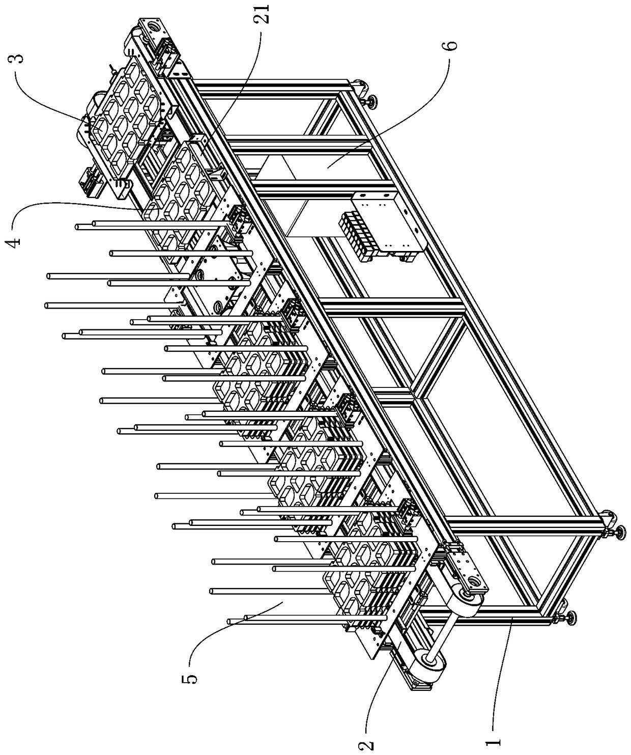
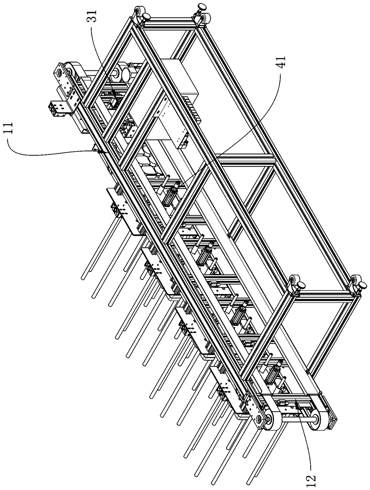
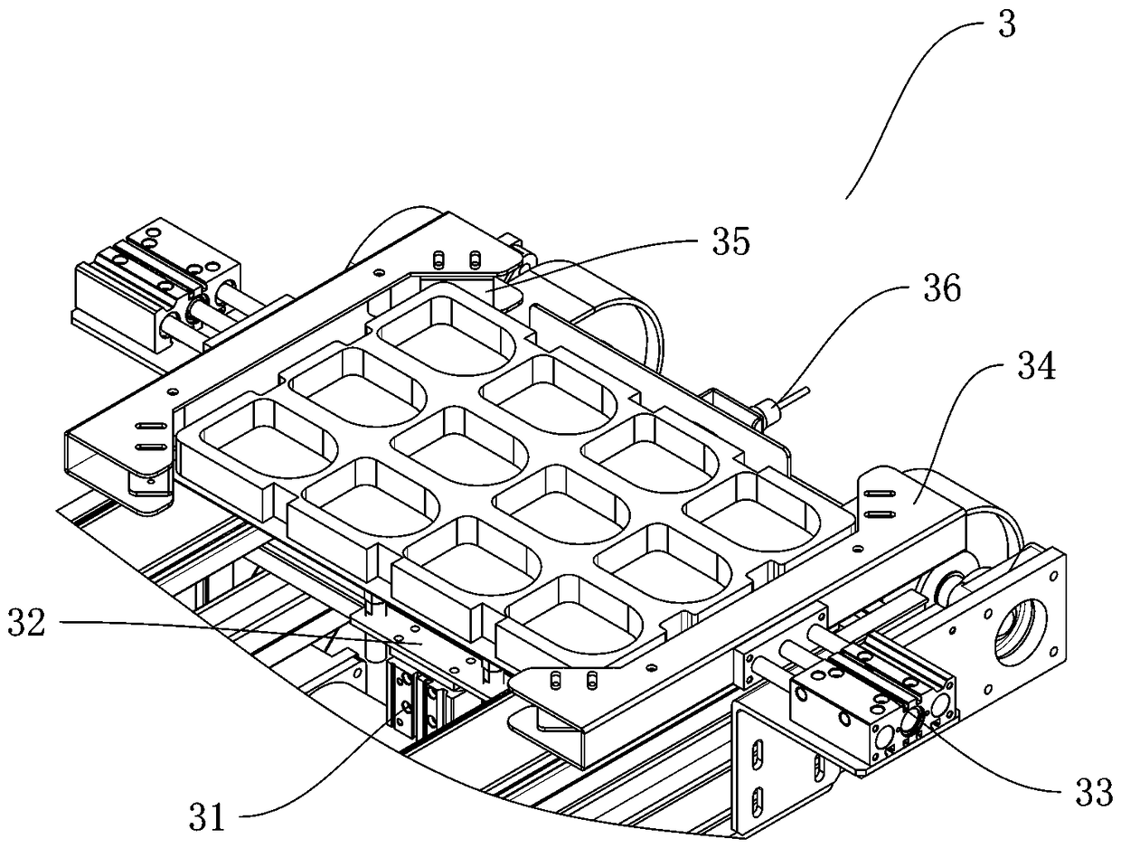
[0025] Figure 1~5 It is a preferred solution of the present invention, including a frame 1, a conveyor belt 2, an assembly positioning mechanism 3, a waiting position 4, a material bin 5 and an electric control box 6.
[0026] The upper part of the frame 1 is a conveying platform composed of two beams 11 and several longitudinal beams 12, the lower part is a support, and the conveyor belt 2 is two plastic chains, which are respectively installed inside the two beams 11 and bypass the longitudinal beams to form a rotary conveyor belt , The two chains on the left and right are spaced apart to form a conveying surface.
[0027] The silo 5, the waiting position 4, and the assembly positioning mechanism 3 are sequentially arranged along the conveying direction from back to fro...
PUM
Abstract
The invention discloses an automatic charging tray feeding system. The system comprises a rack, a conveying belt, an assembling positioning mechanism, a material waiting position, a stock bin and an electric control box, the stock bin, the material waiting position, and the assembling positioning mechanism are arranged from back to front sequentially in the conveying direction, the assembling positioning mechanism comprises a lifting air cylinder, a lifting plate, a positioning air cylinder and positioning clamping claws, a piston rod of the lifting air cylinder is connected with the lifting plate, a charging tray is lifted to the positioning face, the two positioning clamping claws limit the charging tray to the position over the conveying belt, the stock bin comprises a discharging frame, a lifting mechanism and a dividing clamping claw, the lifting mechanism lifts the bottom charging tray to the conveying belt, and the dividing clamping jaw lifts remaining charging trays. Continuousfeeding can be ensured, the feeding position precision is greatly improved, the correcting rate of the next procedure can be ensured, the whole structure is ingenious and fine, in combination with sensors of mechanisms, the feeding process automation is achieved through a PLC, the labor intensity of a worker is greatly reduced, production cost is reduced, and production efficiency and productionprecision are improved.
Description
technical field [0001] The invention relates to the field of automation equipment, in particular to an automatic feeding system for trays. Background technique [0002] Today automation technology has been widely used in industry, agriculture, military, scientific research, transportation, commerce, medical care, services and households. The use of automation technology can not only liberate people from heavy physical labor, part of mental work, and harsh and dangerous working environments, but also expand human organ functions, greatly improve labor productivity, and enhance human ability to understand and transform the world. . [0003] Boxes are commonly used items in people's daily life, such as pencil cases, earphone cases, glasses cases, etc., mostly plastic products with upper and lower cover structures. These products have different shapes, and assembly through automated production can greatly improve production efficiency and reduce Artificial labor intensity. Du...
Claims
Application Information
Patent Timeline
Application Date:The date an application was filed.
Publication Date:The date a patent or application was officially published.
First Publication Date:The earliest publication date of a patent with the same application number.
Issue Date:Publication date of the patent grant document.
PCT Entry Date:The Entry date of PCT National Phase.
Estimated Expiry Date:The statutory expiry date of a patent right according to the Patent Law, and it is the longest term of protection that the patent right can achieve without the termination of the patent right due to other reasons(Term extension factor has been taken into account ).
Invalid Date:Actual expiry date is based on effective date or publication date of legal transaction data of invalid patent.