Operating retractor for general surgery

A technique for surgery and general surgery, applied in the field of medical equipment, can solve problems such as unfavorable surgery, waste of labor, too flat end of the plate hook, etc., and achieve the effects of simplifying the operation steps, improving product quality, and saving operation time

Inactive Publication Date: 2019-03-19
深圳市大豪斯智能科技有限公司
View PDF1 Cites 1 Cited by
  • Summary
  • Abstract
  • Description
  • Claims
  • Application Information

AI Technical Summary

Problems solved by technology

[0002] When carrying out surgical operations, it is necessary to use retractors to separate the skin or other body tissues covered above the surgical site, exposing the surgical site for surgery. The surgical retractors in the prior art are mostly welded and supported by stainless steel rods, and should be made of stainless steel strips However, the shortcoming of the plate hook is that the end is too gentle, and the skin or other internal tissues that are pulled apart by the plate hook often appear to be "unhooked" during the operation. Other internal tissues are torn, which is very unfavorable for doctors to use, and most of the board hooks currently used still have a straight part that is held by the hand, which easily makes the user feel tired or unable to exert strength during use. If you are careful, it is very easy to hurt people, and there is a potential safety hazard. During general surgery in a hospital, it is necessary to use a surgical retractor to pull the surgical incision for surgical operation. At present, the surgical retractors used in hospitals are mostly single hooks with limited width, which is not suitable for The large-scale surgical field of view is exposed, and the length of the handle of the retractor cannot be adjusted. It can only be pulled by the hand of the medical staff. In technology, for example, the invention patent with application number 201220702461.X includes a draw hook and a draw hook arm. The front part of

Method used


Image

  • Operating retractor for general surgery
  • Operating retractor for general surgery
  • Operating retractor for general surgery

Examples


Embodiment Construction

[0019] The following will clearly and completely describe the technical solutions in the embodiments of the present invention with reference to the accompanying drawings in the embodiments of the present invention. Obviously, the described embodiments are only some of the embodiments of the present invention, not all of them. Based on the embodiments of the present invention, all other embodiments obtained by persons of ordinary skill in the art without making creative efforts belong to the protection scope of the present invention.

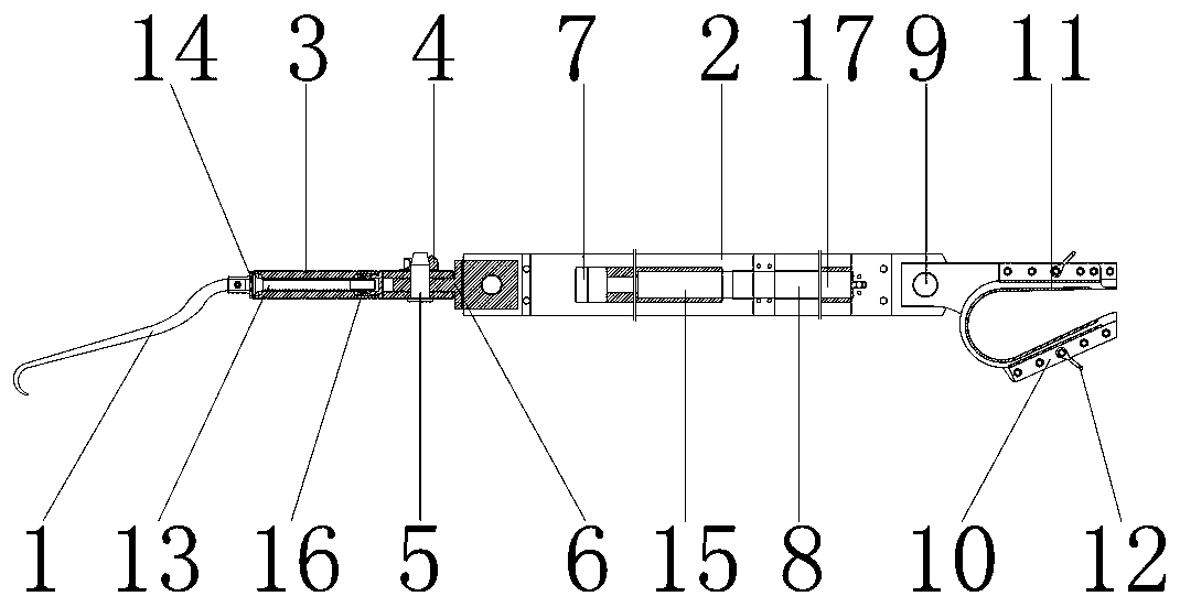
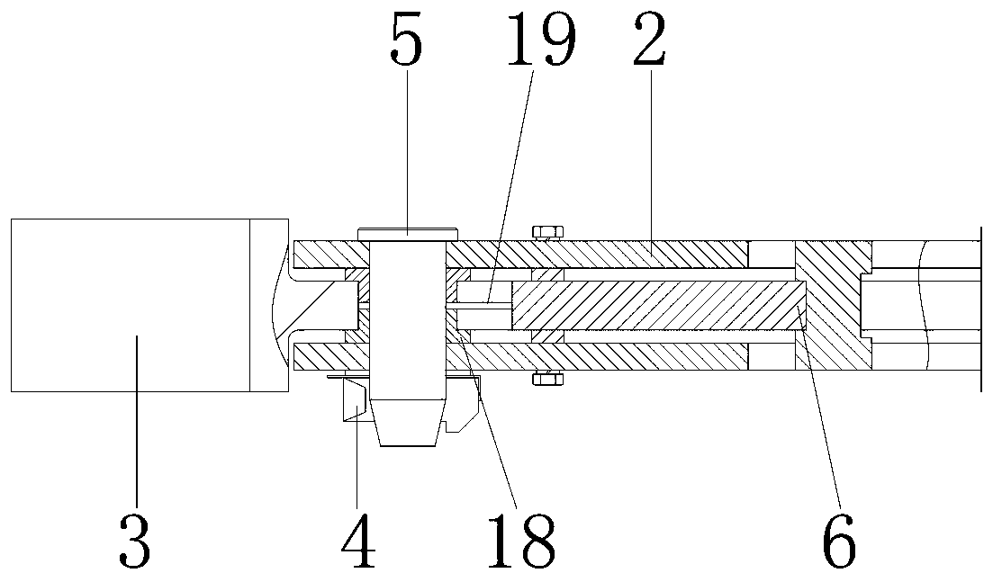
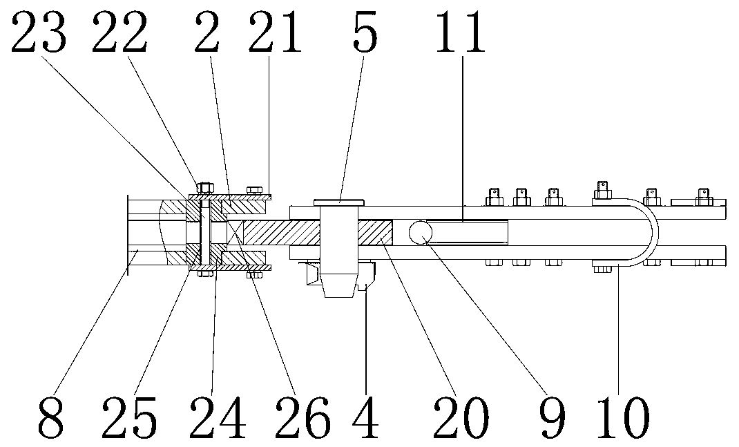
[0020] see Figure 1-3, the present invention provides a technical solution: a retractor for general surgery, including a retractor 1 for positioning the patient's incision, a hook rod 3 is provided on the right side of the retractor 1 for connecting and fixing a rotating rod 13, the hook The inwall of bar 3 is equipped with bar seat 16, is used for fixing rotating bar 13, and the outer wall of bar seat 16 links to each other with the right side ...


PUM


Abstract

The invention discloses an operating retractor for general surgery, comprising a retraction hook. A hook bar is arranged on the right side of the retraction hook; a bar holder is mounted on the innerwall of the hook bar; the outer wall of the bar holder is connected with the right inner wall of the hook bar; the left outer wall of the bar holder is connected with the right outer wall of a rotarybar; a rotary head is mounted on the left outer wall of the rotary bar; the right outer wall of the rotary head is connected with the left outer wall of the rotary bar; the retraction hook is mountedon the inner wall of the rotary head. The operating retractor for general surgery has the advantages that the retraction hook is fixed to the affected part during working, workload and pressure easilycaused to medical personnel and causing working fatigue of the medical personnel can be relieved, an existing operating retractor can be better recognized in the market, the quality of the operatingretractor for general surgery is improved, operating time is saved for medical personnel, operating steps are simplified, waste of medical instrument resources is avoided, and the operating retractorfor general surgery is suitable for popularization and use.

Description

technical field [0001] The invention relates to the technical field of medical equipment, in particular to a retractor for general surgery. Background technique [0002] When carrying out surgical operations, it is necessary to use retractors to separate the skin or other body tissues covered above the surgical site, exposing the surgical site for surgery. The surgical retractors in the prior art are mostly welded and supported by stainless steel rods, and should be made of stainless steel strips However, the shortcoming of the plate hook is that the end is too gentle, and the skin or other internal tissues that are pulled apart by the plate hook often appear to be "unhooked" during the operation. Other internal tissues are torn, which is very unfavorable for doctors to use, and most of the board hooks currently used still have a straight part that is held by the hand, which easily makes the user feel tired or unable to exert strength during use. If you are careful, it is v...

Claims


Application Information

Patent Timeline
IPC IPC(8): A61B17/02
CPCA61B17/02
Inventor 曹军峰
Owner 深圳市大豪斯智能科技有限公司
Why Eureka
Try Eureka