
Differentiable rendering pipeline for inverse graphics

A graphics rendering, a part of the technology, applied in the field of differentiable rendering pipelines, can solve the problems of restricting the adaptability and versatility of reverse graphics systems

Active Publication Date: 2019-03-15
NVIDIA CORP
View PDF5 Cites 11 Cited by
  • Summary
  • Abstract
  • Description
  • Claims
  • Application Information

AI Technical Summary

Problems solved by technology

This specialized code is usually only applicable to a specific object category, thus limiting the adaptability and versatility of prior art reverse graphics systems

Method used


Image

  • Differentiable rendering pipeline for inverse graphics
  • Differentiable rendering pipeline for inverse graphics
  • Differentiable rendering pipeline for inverse graphics

Examples


Embodiment Construction

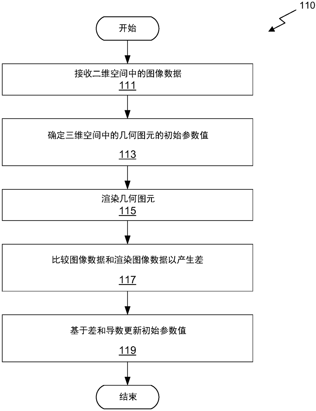
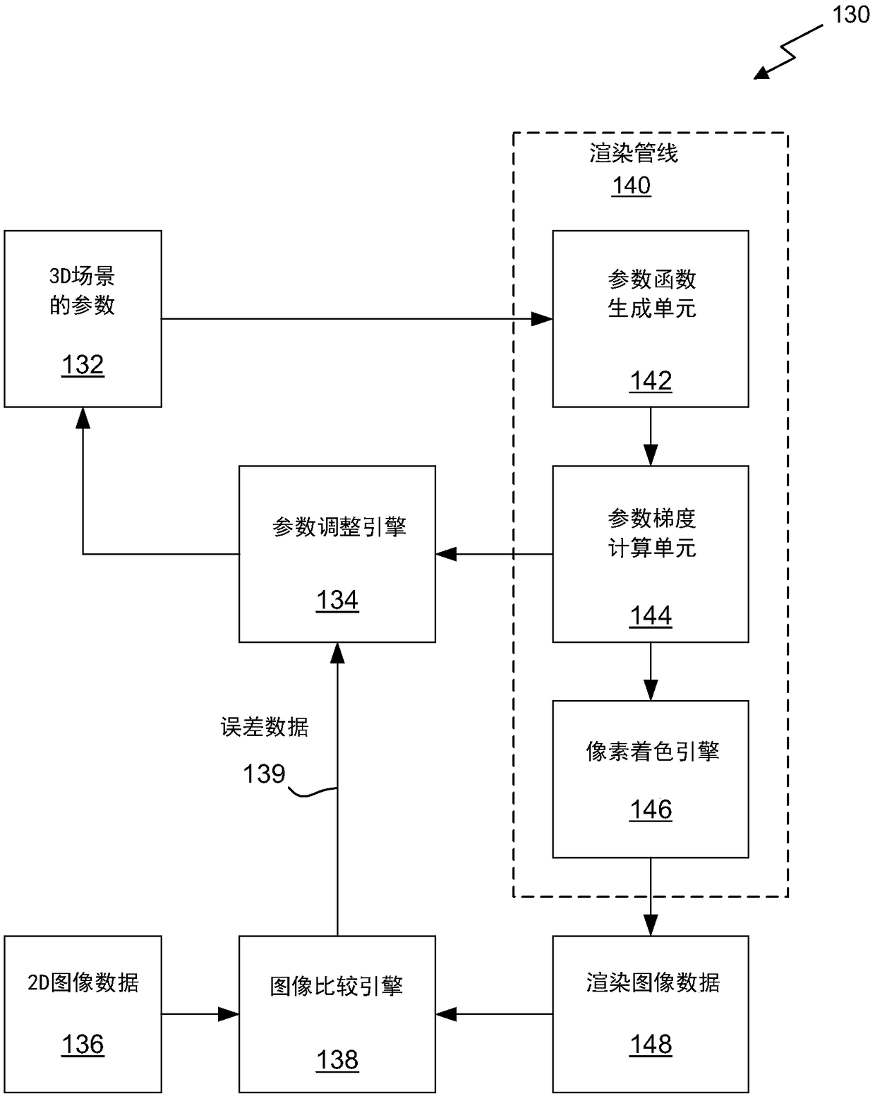
[0029] Embodiments of the invention include an inverse graphics system configured to generate a 3D scene and / or object model of the observed image. These models can include parameters describing arbitrary geometry, lighting, and textures in the observed image. Inverse graphics systems may include rendering pipelines structured to provide end-to-end differentiability for parameters, allowing efficient use of parameter optimization techniques such as gradient descent and the like.

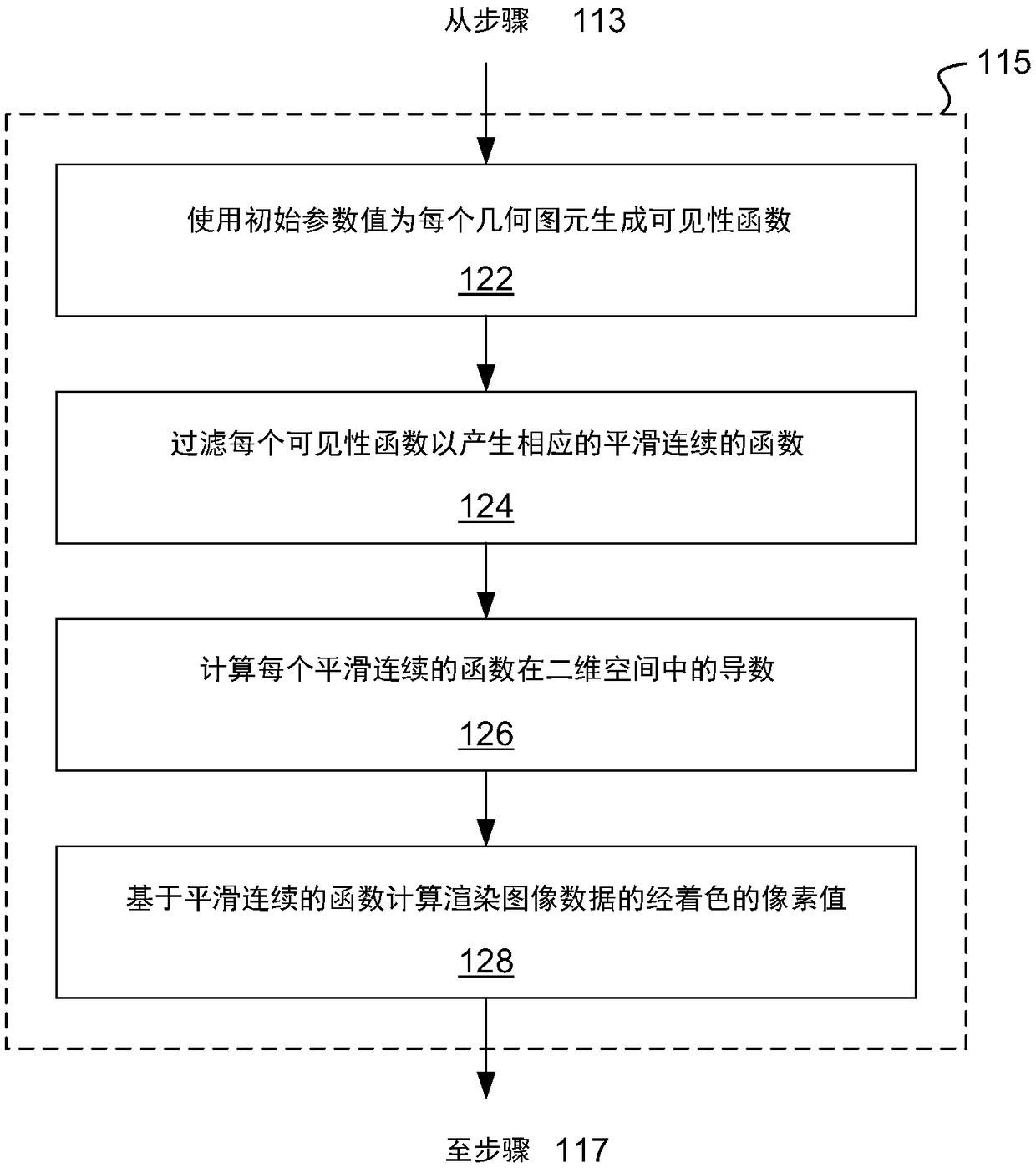
[0030] Visibility is a general discrete (non-differentiable) property of object geometry that is handled by typical prior art rendering pipelines. In one embodiment, visibility filtering and smoothing are used to make visibility continuous, and thus differentiable. Exemplary filtering and smoothing techniques are described herein. By transforming visibility from a discontinuous property to a continuous property, the disclosed rendering pipeline can provide end-to-end differentiability.

[0031] ...


PUM


Abstract

Provided is a system, a method, and a computer readable medium for inverse graphics rendering. The system comprises a differentiable rendering pipeline and a gradient descent optimization engine. A given scene is described using scene parameters. Visibility functions, and other rendered functions, are constructed to be continuous and differentiable, allowing the optimization engine and the rendering pipeline to efficiently iterate through increasingly refined scene models.

Description

[0001] claim priority [0002] This application claims U.S. Provisional Application No. 62 / 554,943, entitled "END-TO-END DIFFERENTIABLE RENDERING PIPELINE FOR INVERSE GRAPHICS," filed September 6, 2017 (Attorney Docket No. NVIDP1187+ / 17KI0185US01), the entire contents of which are incorporated herein by reference. technical field [0003] The present invention relates to computer-generated graphics, and more particularly, to a differentiable rendering pipeline for inverse graphics. Background technique [0004] An inverse graphics system generates a three-dimensional (3D) scene model from one or more images of an observed scene. The 3D scene model may include one or more 3D object models and one or more lighting sources in the observed scene, with the goal of faithfully reproducing object model geometry and scene lighting. State-of-the-art inverse graphics systems typically perform object model generation and optimization using specialized code designed to recognize model...

Claims


Application Information

Patent Timeline
Patent Type & Authority Applications(China)
IPC IPC(8): G06T17/00G06T15/50G06T1/20
CPCG06T1/20G06T15/50G06T17/00G06N3/084G06N3/045G06T11/006G06T15/005G06T15/60G06F17/13
Inventor T-M·李M·萨尔维J·T·莱赫蒂宁A·E·勒福恩
Owner NVIDIA CORP
Learn More