
Pressure balance device and suction cup using the same

A technology of balancing device and pressure, applied in suction cups, connecting components, mechanical equipment, etc., can solve problems such as inability to achieve curved surface adsorption, lack of airtight devices, etc.

Active Publication Date: 2019-03-15
东莞友颉实业有限公司
View PDF23 Cites 0 Cited by
  • Summary
  • Abstract
  • Description
  • Claims
  • Application Information

AI Technical Summary

Problems solved by technology

[0002] Suction cups on the market include suction cups that can absorb smooth surfaces such as glass. In recent years, suction cups that can absorb rough surfaces have appeared; ; One of the reasons is that there is a lack of a device to achieve airtightness between the surface to be adsorbed and the body of the suction cup

Method used


Image

  • Pressure balance device and suction cup using the same
  • Pressure balance device and suction cup using the same
  • Pressure balance device and suction cup using the same

Examples


Embodiment 1

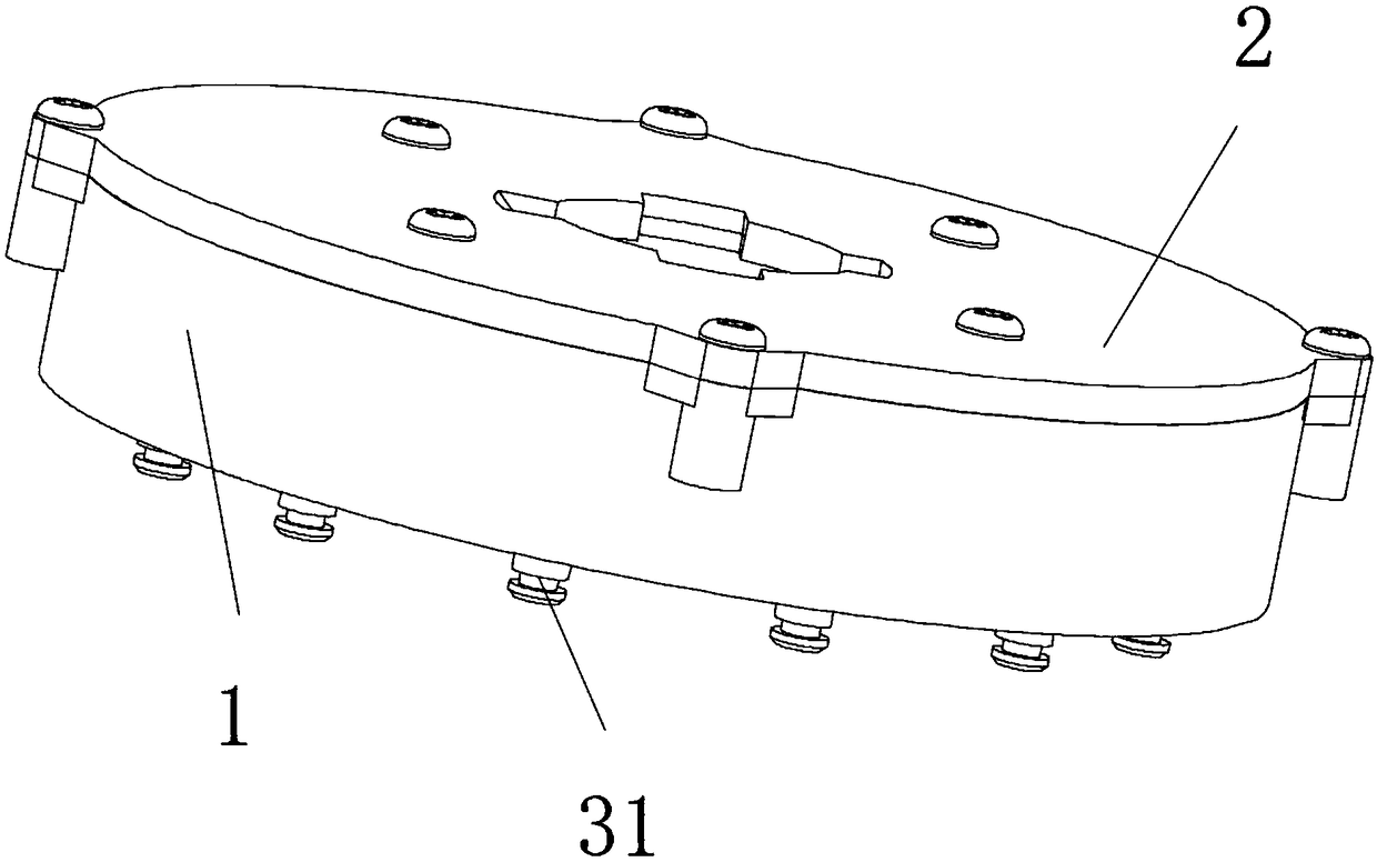
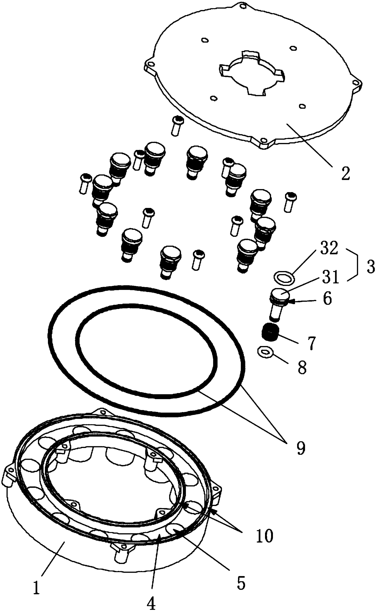
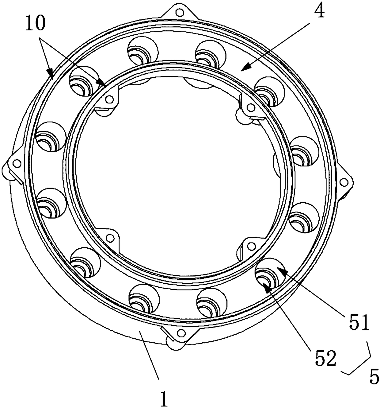
[0024] Such as Figure 1-4 As shown, a pressure balance device includes a base 1, a deformation medium accommodated in the base 1 and capable of being squeezed and deformed, a sealing cover 2 covering the base 1, and a plurality of The connected seal 3, the base 1 is provided with a storage tank 4 for accommodating the deformation medium, the bottom wall of the storage tank 4 is provided with an accommodating through hole 5, and the seal 3 protrudes out of the accommodating through hole 5. The bottom of the hole 5 abuts against the side wall of the accommodating through hole 5, and an airtight cavity is formed between the inner wall of the storage tank 4, the sealing member 3 and the sealing cover 2; when the deformation medium is squeezed by a part of the sealing member , the deformation medium is deformed to squeeze another part of the seal to protrude outward.

[0025] The combination of the base 1, the sealing cover 2 and the sealing member 3 makes the storage tank 4 form...

Embodiment 2

[0047] The difference between this embodiment and embodiment 1 is:

[0048] The sealing member 3 is a sealing column 31 , and the sealing column 31 is a soft rubber sealing column. The soft rubber sealing column 31 penetrates the bottom of the receiving through hole 5 and abuts against the side wall of the receiving through hole 5 . The soft rubber sealing column is adopted, which has strong expansion ability and is more tightly abutted against the receiving through hole 5, avoiding troubles caused by adding and assembling sealing rings, and saving raw material costs and labor.


PUM


Abstract

The present invention relates to the technical field of suction cups, and in particular to a pressure balance device and a suction cup using the same. The pressure balance device includes a base, a deformation medium received in the base and deformed by extrusion, a sealing cover covering the base, and a plurality of sealing members movably connected to the base, wherein the base is provided witha storage tank for accommodating the deformation medium, the bottom wall of the storage tank is provided with receiving through holes, and the sealing members protrude from the bottoms of the receiving through holes and abut against the side walls of the receiving through holes. A sealed cavity is formed between the inner wall of the storage tank, the sealing members and the sealing cover; when the deformation medium is pressed by a part of the sealing members, the deformation medium is deformed to press the other part of the sealing members to protrude outward. After the pressure balance device is pressed, all the sealing members and the contact surface are equally stressed, and the pressure balance effect is achieved; the pressure balance device is applied to the suction cup, and the suction cup can stably suck on the plane or the curved surface.

Description

technical field [0001] The invention relates to the technical field of suction cups, in particular to a pressure balance device and a suction cup using the same. Background technique [0002] Suction cups on the market include suction cups that can absorb smooth surfaces such as glass. In recent years, suction cups that can absorb rough surfaces have appeared; ; One of the reasons is that there is a lack of a device that will be sealed between the surface to be adsorbed and the suction cup body. Contents of the invention [0003] In order to overcome the disadvantages and deficiencies in the prior art, the object of the present invention is to provide a pressure balance device, when the deformation medium is squeezed by a part of the seal, the deformation medium is deformed to squeeze the other part of the seal to protrude outward , so that the other part of the seal is forced and moves along the direction close to the contact surface, and finally all the seals are in con...

Claims


Application Information

Patent Timeline
Patent Type & Authority Applications(China)
IPC IPC(8): F16B47/00
CPCF16B47/006
Inventor 刘仁友
Owner 东莞友颉实业有限公司
Learn More