


Quick Research
Generate reliable direction feasibility study reports for your R&D in just a few steps.

Technical Q&A
Discover and master advanced knowledge NOW. Basics, ideas, possibilities, all at once.

Find Solutions
As an expert in R&D theories, this can generate solutions to your technical problems instantly.

Evaluate Feasibility
Analyze your overall solution with one click, know your potential R&D risks in advance.

Monitor Landscape
Get weekly tech updates, stay abreast of the latest tech innovations and key insights.
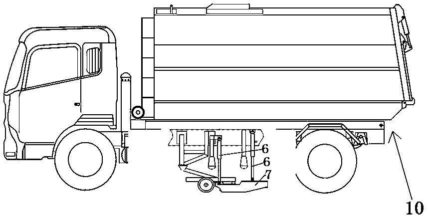
Sweeper
A cleaning vehicle and vehicle frame technology, applied in the field of cleaning vehicles, can solve the problem of inconvenient adjustment of the height from the ground, and achieve the effect of solving the inconvenient adjustment of the height from the ground
- Summary
- Abstract
- Description
- Claims
- Application Information
AI Technical Summary
Problems solved by technology
Method used
Image


Examples
specific Embodiment 4
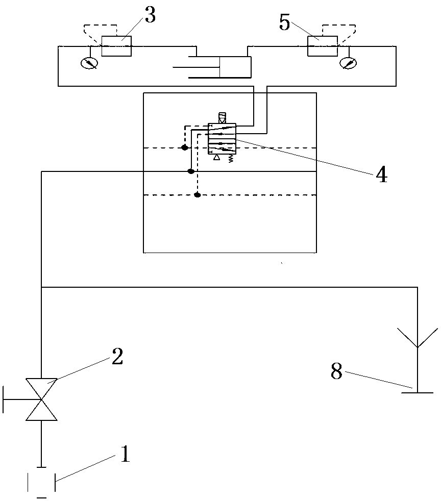
[0028] The specific embodiment 4 of the cleaning vehicle of the present invention, in this embodiment, the air source of the pneumatic control system can also use the air pump of the cleaning vehicle, and the others are the same as in the embodiment 1, and will not be repeated.
specific Embodiment 5
[0029]The specific embodiment 5 of the sweeping vehicle of the present invention uses a plurality of electromagnetic valves to cooperate to realize the on-off control of the gas circuit in this embodiment. Others are the same as the embodiment 1 and will not be repeated.
PUM
 Abstract
Description
Claims
Application Information
 - R&D Engineer
- R&D Manager
- IP Professional
- Industry Leading Data Capabilities
- Powerful AI technology
- Patent DNA Extraction
Browse by: Latest US Patents, China's latest patents, Technical Efficacy Thesaurus, Application Domain, Technology Topic, Popular Technical Reports.
© 2024 PatSnap. All rights reserved.Legal|Privacy policy|Modern Slavery Act Transparency Statement|Sitemap|About US| Contact US: help@patsnap.com