
Test tube centrifuge machine for automatic analyzer

A test-tube centrifuge and automatic analyzer technology, which is applied to centrifuges and other directions, can solve the problems of affecting the separation effect, unfavorable vertical pipette suction of liquid, etc., and achieve the effects of convenient use, simple structure and good separation effect.

Pending Publication Date: 2019-03-12
杨永俊
View PDF12 Cites 7 Cited by
  • Summary
  • Abstract
  • Description
  • Claims
  • Application Information

AI Technical Summary

Problems solved by technology

The newly developed automatic analyzer not only needs to realize the automation of the analysis process, but also wants to realize the automation of the pretreatment preparation stages including sampling, centrifugation, dyeing, etc. However, the tilt angle of the test tubes in the existing test tube centrifuges is fixed, which is not conducive to vertical The straight pipette gun is used for aspirating liquid, and it will form a certain resistance during the speed change process of centrifuge start-high-speed rotation-stop, which will affect the separation effect

Method used


Image

  • Test tube centrifuge machine for automatic analyzer
  • Test tube centrifuge machine for automatic analyzer
  • Test tube centrifuge machine for automatic analyzer

Examples


Embodiment Construction

[0015] The test tube centrifuge used for the automatic analyzer of the present invention comprises a rotating shaft and a test tube placing card, and the rotating shaft and the test tube placing card are connected through an angle adjustment mechanism. Illustrate below by specific embodiment:

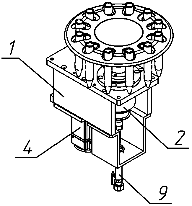
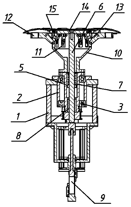
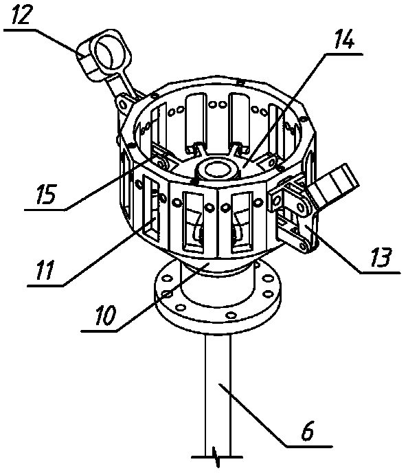
[0016] Such as Figure 1-3 As shown, the angle adjustment mechanism of the present invention includes an outer sleeve 2 fixedly installed on the top plate of the support frame 1, and an inner sleeve 5 is connected with two upper and lower bearings 3 in the outer sleeve 2, and the inner sleeve 5 passes through The synchronous belt transmission mechanism is connected with the motor 4; the inner sleeve 5 is pierced with a rotating shaft 6, and the rotating shaft 6 is pierced with a compression spring 7, and the two ends of the compression spring 7 are respectively provided with upper limits on the inner sleeve 5 block and the lower limit block located on the rotating shaft 6, the joint su...


PUM


Abstract

The invention discloses a test tube centrifuge machine for an automatic analyzer. The test tube centrifuge machine comprises a rotation shaft and test tube containing clamps, and the rotation shaft and the test tube containing clamps are connected through an angle adjusting mechanism. The angle adjusting mechanism comprises an outer sleeve arranged on a supporting frame top plate, the outer sleeveis internally connected with an inner sleeve through bearings, the inner sleeve is driven by a motor, and a rotation shaft penetrates through the inner sleeve and is in cup joint with a compression spring. The joint faces of the rotation shaft and the inner sleeve are provided with mutually-matched spline grooves. A lifting air cylinder connected with a supporting frame bottom plate is correspondingly arranged below the rotation shaft. The top of the inner sleeve is connected with a rotation cage, a plurality of through holes are evenly formed in the side wall of the rotation cage, the test tube containing clamps are hinged to the tops of the through holes, and the test tube containing clamps are provided with rotation arms extending into the through holes. A lifting disc is arranged on the top of the rotation shaft, and the periphery edge of the lifting disc is provided with a plurality of hinge arms correspondingly connected with the rotation arms. By means of the test tube centrifuge machine, the inclination angle of the test tube placement position can be adjusted, operation is convenient, and the best separation effect is achieved.

Description

technical field [0001] The invention relates to the technical field of a test tube centrifuge, in particular to a test tube centrifuge used for an automatic analyzer. Background technique [0002] The test tube centrifuge used in the laboratory is a decanter centrifuge, which includes a drum driven by a motor. There are a number of inclined holes for placing test tubes evenly spaced on the drum. When the drum rotates around its central axis at a high speed At this time, the components with different densities in the suspension in the test tube will rapidly settle and stratify in the centrifugal force field to achieve the purpose of solid-liquid separation. The newly developed automatic analyzer not only needs to realize the automation of the analysis process, but also wants to realize the automation of the pretreatment preparation stages including sampling, centrifugation, dyeing, etc. However, the existing test tube centrifuge has a fixed test tube placement angle, which is...

Claims


Application Information

Patent Timeline
Patent Type & Authority Applications(China)
IPC IPC(8): B04B5/04
CPCB04B5/0421
Inventor 杨永俊
Owner 杨永俊
Learn More