
Positioning and guiding reduction forceps for orthopedics department

A technology for positioning, guiding and resetting forceps, applied in the direction of fixator and other directions, can solve the problems of inconvenient drilling of the drill bit into the bone accurately, inconvenience for medical workers to use, inconvenient adjustment of the length of the forceps handle, etc., and achieves simple structure, reliable clamping, reliable Precisely guided effects

Inactive Publication Date: 2019-03-12
SHANGHAI EAST HOSPITAL
View PDF8 Cites 6 Cited by
  • Summary
  • Abstract
  • Description
  • Claims
  • Application Information

AI Technical Summary

Problems solved by technology

[0002] The current orthopedic reduction forceps cannot achieve reliable clamping and precise guidance when the fracture block is fixed. It is easy to adjust, but not easy to use by medical workers, and cannot meet the needs of medical workers. Therefore, we propose a positioning-oriented orthopedic reduction forceps to solve the above problems

Method used


Image

  • Positioning and guiding reduction forceps for orthopedics department
  • Positioning and guiding reduction forceps for orthopedics department
  • Positioning and guiding reduction forceps for orthopedics department

Examples


Embodiment Construction

[0022] Preferred embodiments of the present invention will be described in detail below.

[0023] The reference signs in the accompanying drawings of the specification include:

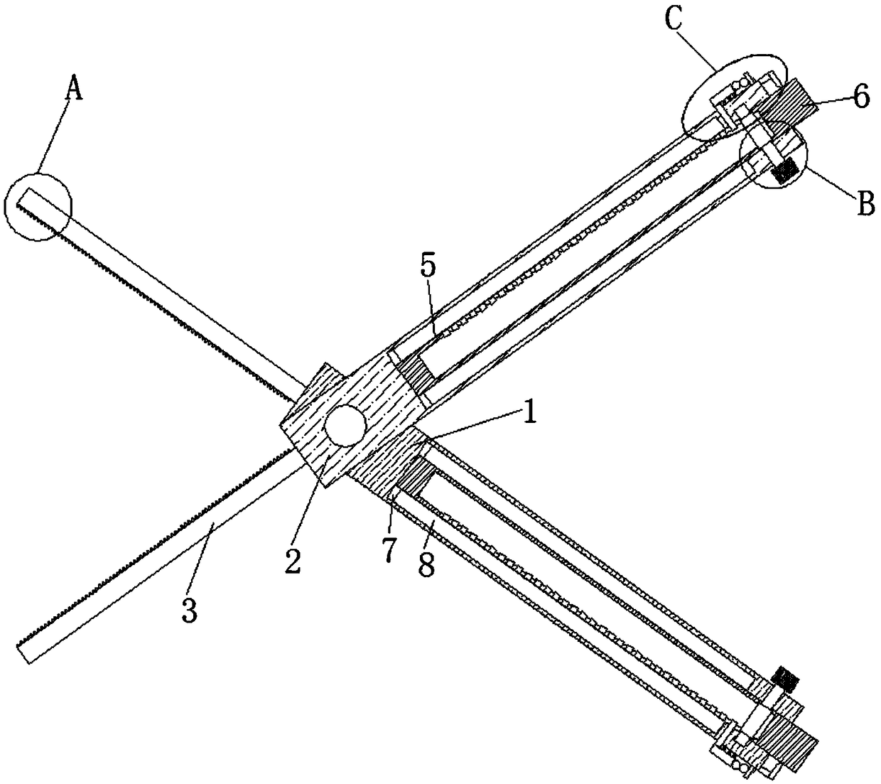
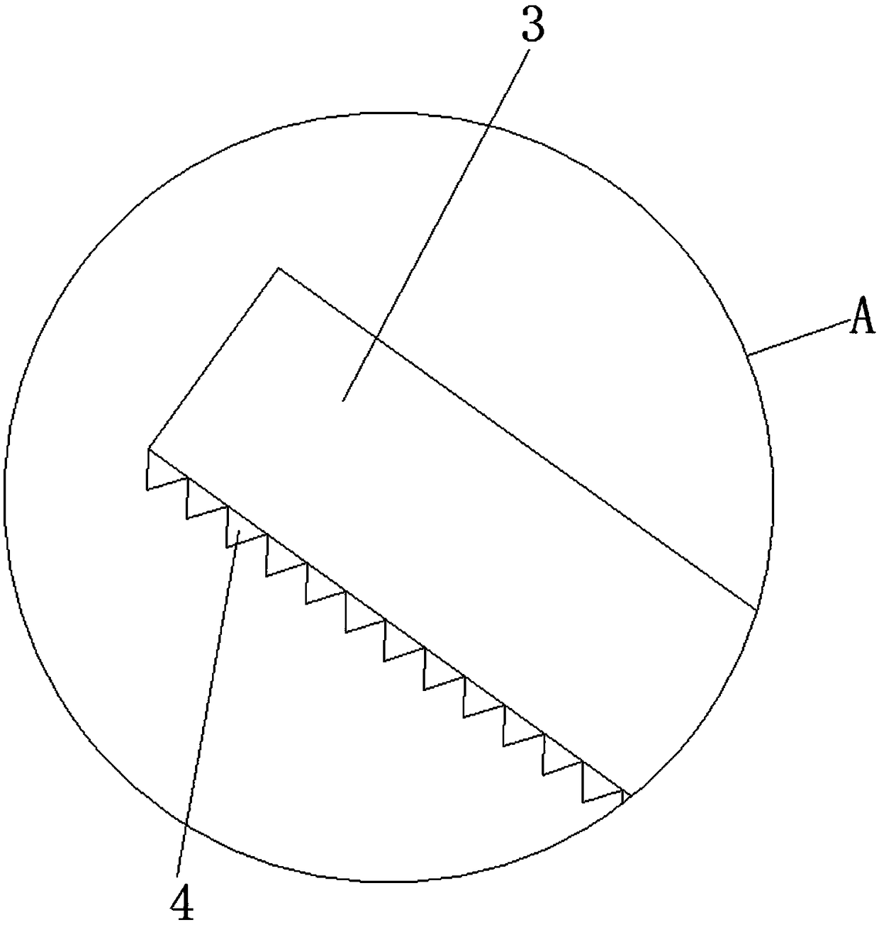
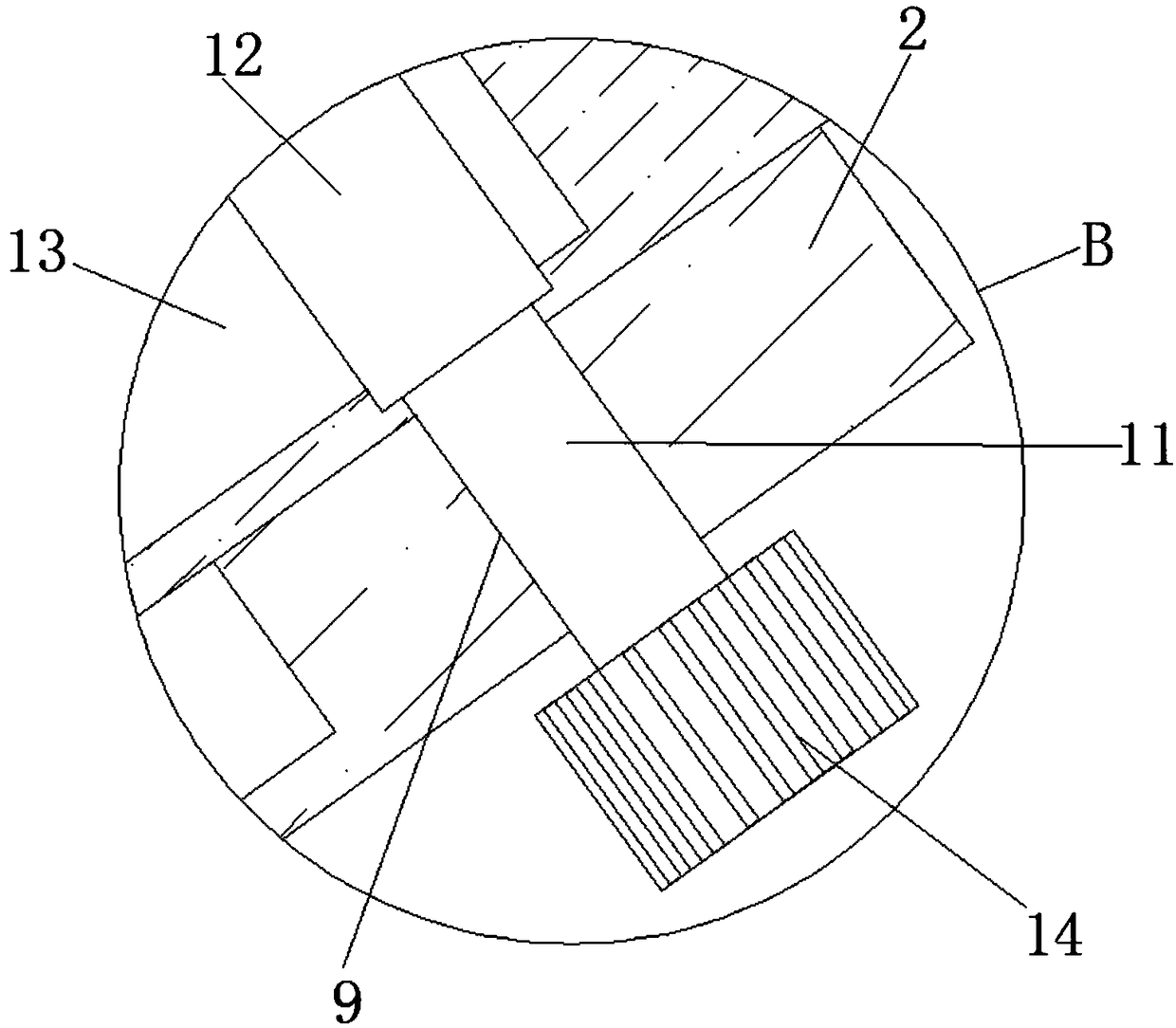
[0024] 1 first clamp handle, 2 second clamp handle, 3 clamp wall, 4 sawtooth, 5 chute, 6 third clamp handle, 7 limit plate, 8 limit slot, 9 rotation hole, 10 rotation slot, 11 rotation shaft, 12 gears, 13 racks, 14 screw handles, 15 vertical holes, 16 vertical plates, 17 fixed slots, 18 traction plates, 19 springs, 20 first balls, 21 moving plates, 22 second balls, 23 connecting plates, 24 pointers .

[0025] Such as Figure 1-5 A positioning-guided orthopedic reduction forceps is shown, comprising a first forceps handle 1 and a second forceps handle 2 hinged with the first forceps handle 1, and one side of the first forceps handle 1 and the second forceps handle 2 are welded with The clamp wall 3 is provided with serrations 4 on one side of the clamp wall 3, and the other side of the first clamp h...


PUM


Abstract

The invention discloses positioning and guiding reduction forceps for the orthopedics department. The positioning and guiding reduction forceps comprise a first forcep handle and a second forcep handle hinged to the first forcep handle, forcep walls are welded to one side of the first forcep handle and one side of the second forcep handle respectively, saw teeth are arranged on one side of each forcep wall, sliding grooves are formed in the other side of the first forcep handle and the other side of the second forcep handle respectively, third forcep handles are slidingly installed in the sliding grooves, limiting plates are welded to the tops and the bottoms of the third forcep handles respectively, limiting grooves are formed in the inner walls of the tops and the inner walls of the bottoms of the sliding grooves respectively, the limiting plates are slidingly installed in the corresponding limiting grooves, rotating holes are formed in the inner walls of the sides, close to each other, of the two sliding grooves respectively, and rotating grooves are formed in the inner walls of the sides, away from each other, of the two sliding grooves respectively. The positioning and guidingreduction forceps are simple in structure and convenient to use, and can reliably clamp and accurately guide bone fracture blocks during fixation, a drill bit is easily and accurately drilled into abone, an operation is completed conveniently and smoothly, the length of the reduction forceps for the orthopedics department can be adjusted, and using requirements of users are met.

Description

technical field [0001] The invention belongs to the technical field of orthopedic reset forceps among medical auxiliary instruments, and in particular relates to a positioning-guided orthopedic reset forceps. Background technique [0002] The current orthopedic reduction forceps cannot achieve reliable clamping and precise guidance when the fracture block is fixed. It is easy to adjust, but not convenient for medical workers to use, and cannot meet the needs of medical workers. Therefore, we propose a positioning-oriented orthopedic reduction forceps to solve the above problems. Contents of the invention [0003] Based on the technical problems existing in the background technology, the present invention proposes a positioning-guided orthopedic reduction forceps. [0004] A positioning-guided orthopedic reduction forceps proposed by the present invention comprises a first forceps handle and a second forceps handle hinged with the first forceps handle, and one side of the ...

Claims


Application Information

Patent Timeline
Patent Type & Authority Applications(China)
IPC IPC(8): A61B17/88
CPCA61B17/8866
Inventor 季晟超李建锐
Owner SHANGHAI EAST HOSPITAL
Learn More