Rotary suction nozzle device

A technology of pushing device and rotating rod, which is applied in the direction of electrical components, semiconductor/solid-state device manufacturing, circuits, etc., can solve the problems that the suction nozzle device does not have the degree of freedom of rotation and cannot adjust the angle, etc.

Pending Publication Date: 2019-03-08
江苏新智达新能源设备有限公司
View PDF0 Cites 1 Cited by
  • Summary
  • Abstract
  • Description
  • Claims
  • Application Information

AI Technical Summary

Problems solved by technology

[0005] The technical problem to be solved by the present invention is: the existing suction nozzle device has no degree of freedom of rotation and cannot adjust the angle. The present invention provides a rotating suction nozzle device to solve the above problems

Method used


Image

  • Rotary suction nozzle device
  • Rotary suction nozzle device
  • Rotary suction nozzle device

Examples


Embodiment Construction

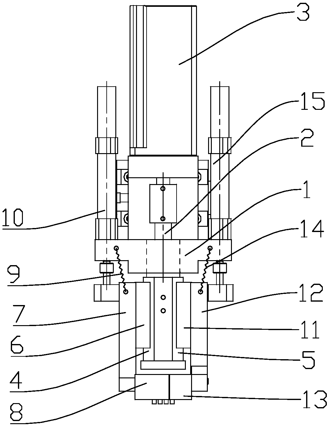
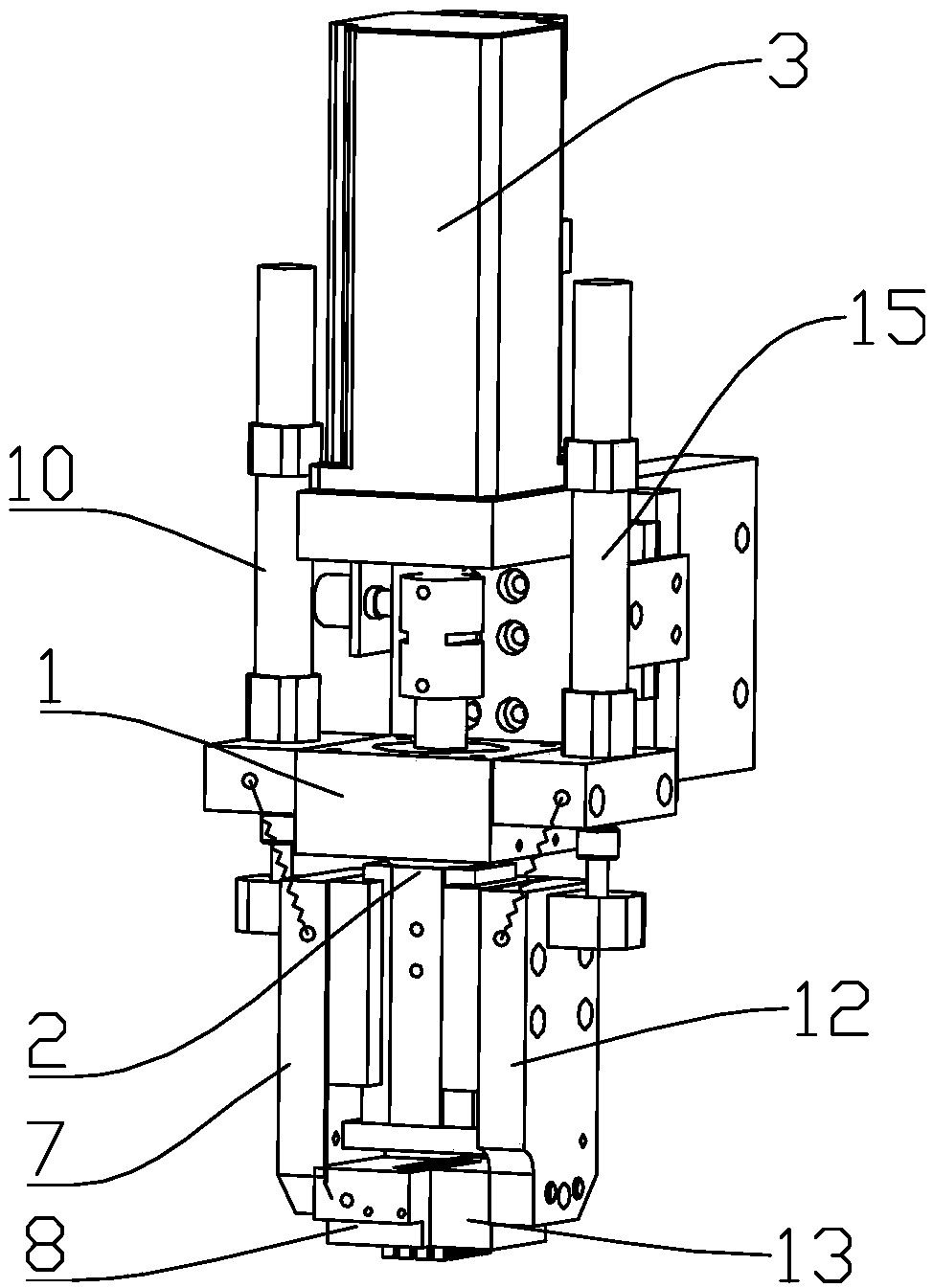
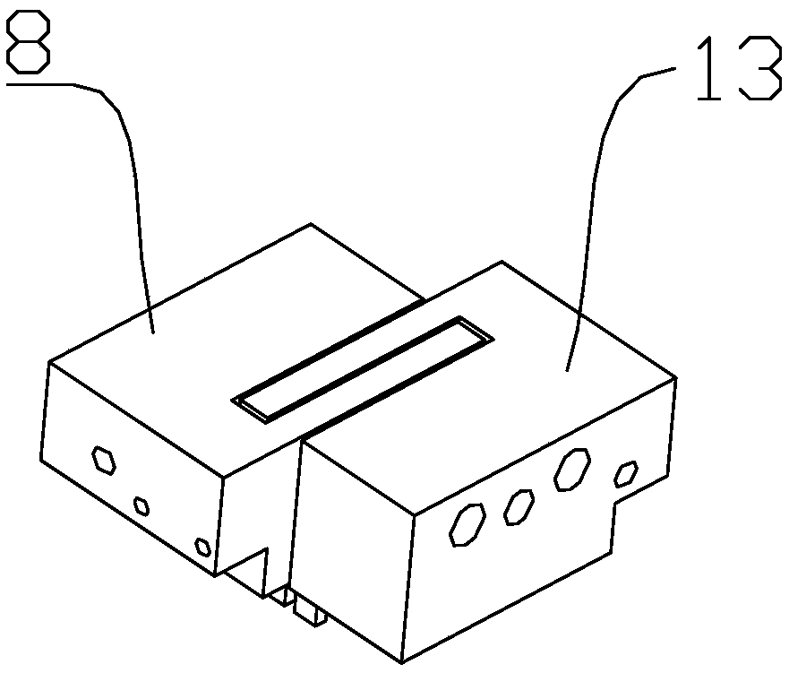
[0017] Embodiments of the present invention are described in detail below, examples of which are shown in the drawings, wherein the same or similar reference numerals designate the same or similar elements or elements having the same or similar functions throughout. The embodiments described below by referring to the figures are exemplary only for explaining the present invention and should not be construed as limiting the present invention. On the contrary, the embodiments of the present invention include all changes, modifications and equivalents coming within the spirit and scope of the appended claims.

[0018] In describing the present invention, it should be understood that the terms "center", "longitudinal", "transverse", "length", "width", "thickness", "upper", "lower", "front", " Back", "Left", "Right", "Vertical", "Horizontal", "Top", "Bottom", "Inner", "Outer", "Axial", "Radial", "Circumferential", etc. The indicated orientation or positional relationship is based ...


PUM


Abstract

The invention provides a rotary suction nozzle device. The rotary suction nozzle device comprises a support and a rotating rod; the support is fixedly arranged, and the rotating rod penetrates the support along a vertical direction; a motor for driving the rotating rod to rotate is arranged above the rotating rod, a first guide rail is vertically arranged at a left side of a lower part of the rotating rod, and a second guide rail is vertically arranged at a right side of the lower part of the rotating rod; a first slide block is slidingly arranged on the first guide rail, a first bracket is arranged on the first slide bock, and a first suction nozzle is arranged at the bottom of the first bracket; a second slide block is slidingly arranged on the second guide rail, a second bracket is arranged on the second slide bock, and a second suction nozzle is arranged at the bottom of the second bracket; by arranging the rotatable rotating rod and arranging the first bracket and the second bracket at two sides of the rotating rod, the suction nozzle device can be rotated after being driven by the motor, and then the first suction nozzle and the second suction nozzle have the rotational freedom when satisfying the crystal-taking and crystal-fixing work, and the problem that the suction nozzles are hard to rotate and adjust is solved.

Description

technical field [0001] The invention relates to the field of semiconductor packaging, in particular to a rotary suction nozzle device. Background technique [0002] SMT is Surface Mount Technology (Surface Mount Technology) (abbreviation of Surface Mount Technology), known as surface mount or surface mount technology. It is the most popular technology and process in the electronic assembly industry. [0003] In the existing SMT field, the common process includes suctioning the die chip from the pick-up station, and then placing it in the blank of the die-bonding station. During crystallization, the method of transporting at the same position is usually adopted, and the wafer chip of the crystal extraction station is transported to the die bonding station through the suction nozzle device. In the prior art, the wafer chip of the crystal retrieval station and the die bonding The positions of wafer chips that need to be bonded are the same at the workstations, and the suction...

Claims


Application Information

Patent Timeline
Patent Type & Authority Applications(China)
IPC IPC(8): H01L21/683
CPCH01L21/6838
Inventor 向军冯霞霞
Owner 江苏新智达新能源设备有限公司
Why Eureka
Try Eureka