Telegraph pole conveying device

A technology for conveying devices and electric poles, which is applied in the direction of conveyors, conveyor objects, transportation and packaging, etc. It can solve the problems of injury to lifters, wear and damage on the surface of electric poles, etc., so as to improve lifting efficiency and reduce labor intensity , the effect of reducing investment

Pending Publication Date: 2019-03-08
杭州金太格电子有限公司
View PDF0 Cites 2 Cited by
  • Summary
  • Abstract
  • Description
  • Claims
  • Application Information

AI Technical Summary

Problems solved by technology

[0002] At the electric power construction site in the field or on the mountain, when there are no vehicles and roads, the whole pole of various specifications can only be transported by manual lifting or by binding the pole with a steel wire rope and then dragging it with a motorized winch. When dragging the pole, because the pole is close to the ground, the surface of the pole will be worn, and the crops or other crops in the field where the pole passes will be damaged in a large area. On the other hand, if the pole is lifted manually, it will cause artificial A lot of investment, low efficiency and high cost of handling, especially when lifting poles on the mountain, due to the slope of the mountain, the weight of the staff lifting the poles is different, which may also cause injury to the staff lifting the poles

Method used


Image

  • Telegraph pole conveying device
  • Telegraph pole conveying device
  • Telegraph pole conveying device

Examples


Embodiment 1

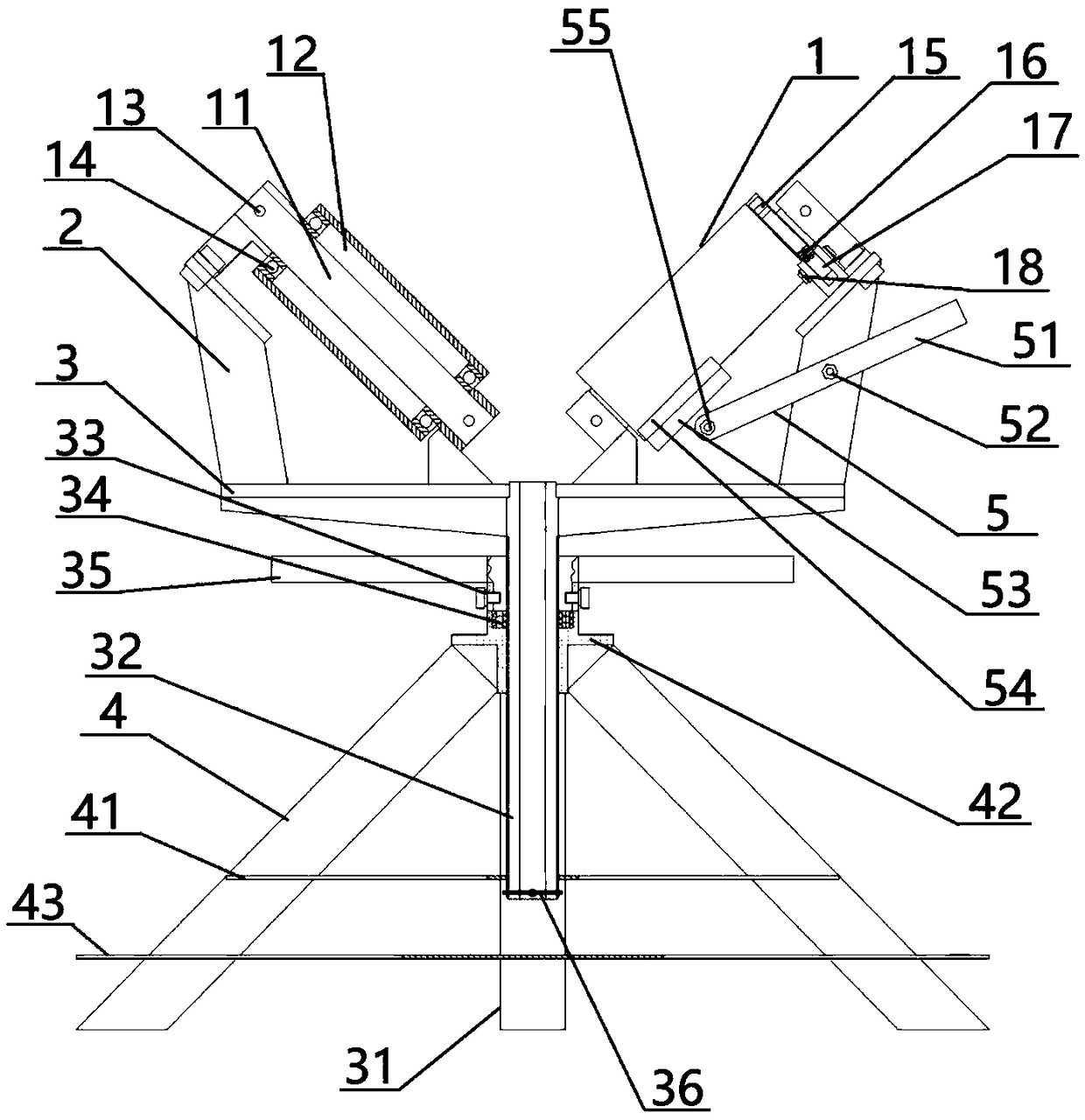
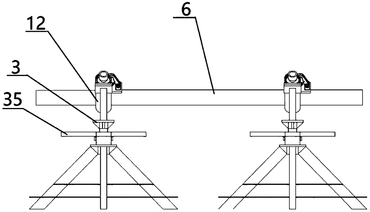
[0022] Such as figure 2 As shown, in the specific use process, when the electric pole 6 needs to be transported over a long distance, the conveying direction is selected, and the first electric pole conveying device ( figure 2 Select the right side as the first pole conveying device, assuming that the pole 6 is conveyed from the right to the left), lift one end of the pole 6 with a wire rope, put it on the pole conveying device, and then push the pole 6 to make the roller 12 Rotate, push the pole 6 up, according to the movement of the center of gravity of the pole 6 on the first pole conveying device, set up the second pole conveying device in time before the center of gravity moves out of the first pole conveying device, Place it in a suitable position. Since the center of gravity of the pole 6 is on the right side of the first pole conveying device at this time, the left side of the pole 6 is tilted up, and the second pole conveying device is directly placed under the left...

Embodiment 2

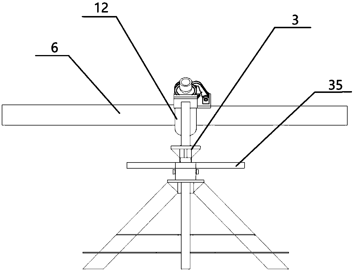
[0025] Such as image 3 As mentioned above, in some sites, it is necessary to adjust the direction of the electric pole 6. At this time, the rotating handle 35 can be turned to bring the lifting screw 32 to the lowest position, and one end of the electric pole 6 can be lifted with a wire rope, mounted on the electric pole conveying device, and pushed Electric pole 6, so that the electric pole 6 can basically be suspended in the air, turn the electric pole 6, and the electric pole 6 can rotate under the cooperation of the turntable 3, and when it is rotated to a suitable angle, the electric pole 6 can be pushed down from the electric pole conveying device, and the electric pole 6 is completed. Adjust the demand for the direction of pole 6. The 180° direction adjustment of the electric pole 6 can be completed by using the electric pole conveying device.


PUM


Abstract

The invention discloses a telegraph pole conveying device. The telegraph pole conveying device comprises roller supports, a rotating disc, supporting legs and at least two roller structures in bilateral symmetry. Each roller structure comprises a main shaft and a roller. The rollers are in a V shape, the rollers are arranged on the main shafts in a sleeving manner to rotate, the main shafts are erected on the rotating disc through the roller supports, and the rotating disc is arranged on the supporting legs. A telegraph pole is erected between the rollers and is conveyed by means of rotating of the rollers. The telegraph pole conveying device has the advantages that the traditional manner that the telegraph pole is carried manually or bundled by a steel wire rope and then is pulled throughmechanical winching and traction is replaced, the input of a large number of carrying personnel is reduced, hurt to the carrying personnel and large-area damage of crops are avoided, the labor intensity of the carrying personnel is reduced, and the carrying efficiency of the telegraph pole is improved.

Description

technical field [0001] The invention relates to an outdoor electric pole conveying device, in particular to an electric pole conveying device. Background technique [0002] At the electric power construction site in the field or on the mountain, when there are no vehicles and roads, the whole pole of various specifications can only be transported by manual lifting or by binding the pole with a steel wire rope and then dragging it with a motorized winch. When dragging the pole, because the pole is close to the ground, the surface of the pole will be worn, and the crops or other crops in the field where the pole passes will be damaged in a large area. On the other hand, if the pole is lifted manually, it will cause artificial The investment is large, the efficiency of handling is low, and the cost is high, especially when lifting the pole on the mountain. Due to the slope of the mountain, the weight of the person lifting the pole is different, which may also cause injury to th...

Claims


Application Information

Patent Timeline
Patent Type & Authority Applications(China)
IPC IPC(8): B65G13/02B65G13/075B65G39/12
CPCB65G13/02B65G13/075B65G39/12B65G2201/0217
Inventor 郑华彪郑若愚王艺轩郑华虎黄文敏王以武毛台凌翌俞彬姜涛
Owner 杭州金太格电子有限公司
Why Eureka
Try Eureka