
Holographic large image generation system

An image and holographic technology, applied in the field of holographic large images

Inactive Publication Date: 2002-11-13
康斯坦丁·罗格兹
View PDF2 Cites 1 Cited by
  • Summary
  • Abstract
  • Description
  • Claims
  • Application Information

AI Technical Summary

Problems solved by technology

This will be mainly used for advertising and entertainment

Method used


Image

  • Holographic large image generation system
  • Holographic large image generation system
  • Holographic large image generation system

Examples


Embodiment Construction

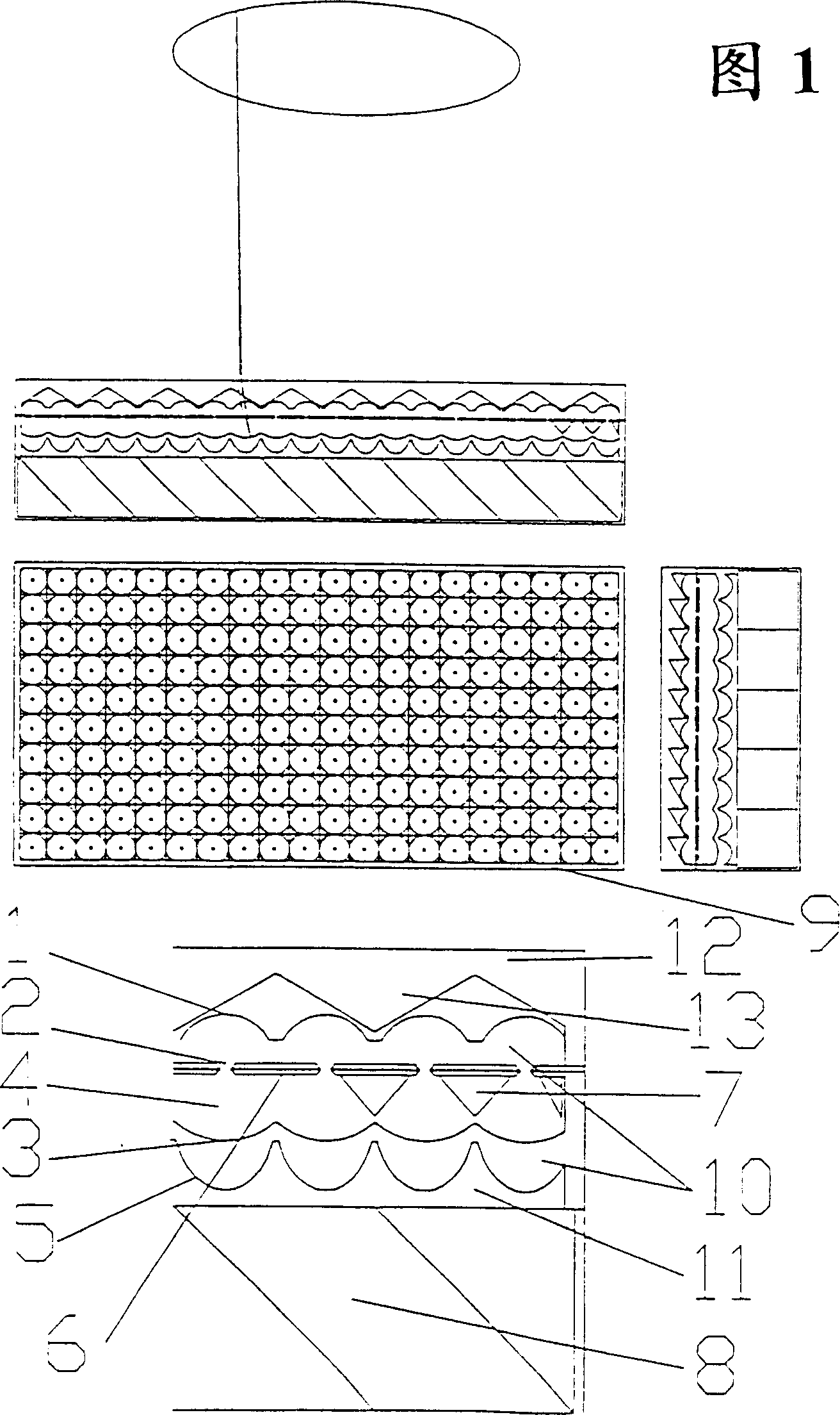
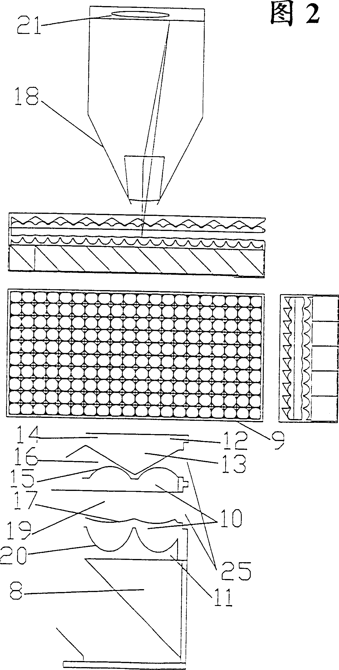
[0042] In Fig. 1 a front view of the projection screen can be seen, followed by a top view and a side view; the same applies to Fig. 2 as well. The symbols used in the accompanying drawings have the following meanings:

[0043] 1. Spherical lens,

[0044] 2. Aperture with multiple aperture holes,

[0045] 3. The imaging surface coated with the photosensitive layer,

[0046] 4. The hollow space between the imaging surface 3 and the aperture,

[0047] 5. Aspheric lens,

[0048] 6. Used to indicate the closing mechanism of the aperture hole 2,

[0049] 7. Magnets on the aperture, which can be operated from the outside by means of electromagnets not shown,

[0050] 8. Outline a prism system that redirects light so that the aspheric lens 5 or imaging surface 3 is illuminated from behind,

[0051] 9. For light components,

[0052] 10. For the lens plate,

[0053] 11. Refers to the prism system, and

[0054] 12. For the light board,

[0055] 13. is a deflecting prism, and ...


PUM


Abstract

A set of enhanced apparatuses and a computer integrated processes are provided for creating large scale 3D integral photography images. A large number of mini projectors in a grid on top of each other and beside each other, are exposed individually with a computer calculated reverse (pseudoscopic) perspective image. The curved photo layer inside the projectors obtains sharp high resolution images through the achromatic behavior of the lens system. A guided back light system directs the light from the back through the diaphragm apertures.

Description

technical field [0001] The present invention relates to a method for producing a large holographic image of an object, which comprises a plurality of image projectors arranged horizontally and vertically in grid order, and a device for implementing the method. The invention also relates to a device and a method by which a three-dimensional virtual object can be represented on a screen, which can be observed from various angles without the aid of special glasses. Background technique [0002] Methods of holographic image generation are already known. In stereophotography, two slightly offset images are taken or calculated. They must be transmitted separately to the respective eyes of the viewer. The viewer must see through a device or glasses that separate the images, where the viewing angle cannot be changed. [0003] In laser holography, a photosensitive plate is exposed to a laser beam reflected from an object and a previously diverted reference beam. However, the holo...

Claims


Application Information

Patent Timeline
Patent Type & Authority Patents(China)
IPC IPC(8): G02B27/22G03B35/00G03B35/18G03B35/24G03B37/04
CPCG03B35/24G03B37/04H04N1/00201G02B30/27
Inventor 康斯坦丁·罗格兹
Owner 康斯坦丁·罗格兹
Learn More