Air intake structure of an electric propulsion engine
An air intake structure and engine technology, which is applied to machines/engines, mechanical equipment, thrust reversers, etc., can solve the problems of reduced engine body volume and complicated engine propellant supply, and achieve the effect of compact sealing structure
- Summary
- Abstract
- Description
- Claims
- Application Information
AI Technical Summary
Problems solved by technology
Method used
Image
Examples
Embodiment Construction
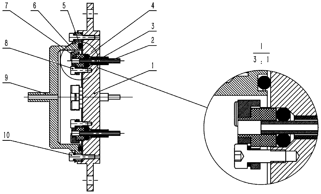
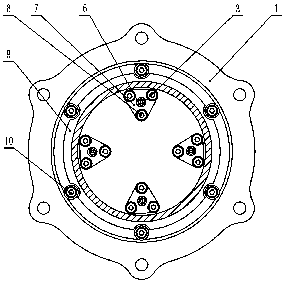
[0019] Attached below Figure 1~2 Specific embodiments of the present invention will be described.
[0020] The present invention is an electric propulsion engine air intake structure, the main components include engine body flange 1, gas distributor pipeline 2, insulating ceramic tube 3, gas distributor pipeline-sealing ring 4, air intake chamber-sealing ring 5. Gas distributor pipeline-ceramic terminal 6, gas distributor pipeline-press sheet 7, gas distributor pipeline-fastening bolt 8, inlet flange 9, connecting bolt 10.
[0021] to combine figure 1 , taking the engine body flange 1 as a reference, insert four insulating ceramic tubes 3 from the right side into four 4mm small holes on the engine body flange 1, and the left end surface of the insulating ceramic tube 3 is connected to the engine body flange 1 Align the cone edges.
[0022] to combine figure 1 , Insert the four gas distributor pipelines 2 into the four insulating ceramic tubes 3 from the right side, and th...
PUM
 Abstract
Description
Claims
Application Information
 - R&D
- Intellectual Property
- Life Sciences
- Materials
- Tech Scout
- Unparalleled Data Quality
- Higher Quality Content
- 60% Fewer Hallucinations
Browse by: Latest US Patents, China's latest patents, Technical Efficacy Thesaurus, Application Domain, Technology Topic, Popular Technical Reports.
© 2025 PatSnap. All rights reserved.Legal|Privacy policy|Modern Slavery Act Transparency Statement|Sitemap|About US| Contact US: help@patsnap.com


