High-voltage-driven LED light-emitting device

A light-emitting device and high-voltage drive technology, which is applied to semiconductor devices of light-emitting elements, components of lighting devices, light sources, etc., can solve problems such as unapplied warning fields, and achieve the effects of easy movement, improved safety, and strong flexibility

Pending Publication Date: 2019-02-26
山东聚芯光电科技有限公司
View PDF0 Cites 0 Cited by
  • Summary
  • Abstract
  • Description
  • Claims
  • Application Information

AI Technical Summary

Problems solved by technology

However, it has not yet been applied to the field of warning

Method used


Image

  • High-voltage-driven LED light-emitting device
  • High-voltage-driven LED light-emitting device

Examples


Embodiment Construction

[0014] In order to make the purpose, technical solutions and advantages of the embodiments of the present invention clearer, the technical solutions in the embodiments of the present invention will be clearly and completely described below in conjunction with the drawings in the embodiments of the present invention. Obviously, the described embodiments It is a part of embodiments of the present invention, but not all embodiments. Based on the embodiments of the present invention, all other embodiments obtained by persons of ordinary skill in the art without creative efforts fall within the protection scope of the present invention.

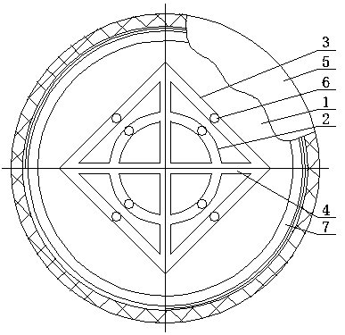
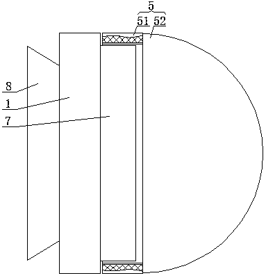
[0015] A high-voltage driven LED light-emitting device, as shown in the figure, includes a base 1. Several annular grooves 2 with different diameters are opened on the front of the base 1. The annular grooves 2 are all collinear with the center line of the base 1. The front of the base 1 is provided with The rectangular ring groove 3 and the ring ...


PUM


Abstract

A high-voltage-driven LED light-emitting device comprises a base. A plurality of annular grooves with different diameters are formed in the front side of the base, and all the annular grooves are collinear with the center line of the base; a rectangular ring groove is formed in the front side of the base, all the annular grooves are located in the rectangular ring groove, and the rectangular ringgroove is collinear with the center lines of the annular grooves; two perpendicular strip-shaped grooves are formed in the front side of the base, the two ends of the strip-shaped grooves are connected with the across corners of the rectangular ring groove respectively, and the strip-shaped grooves are communicated with the interiors of the strip-shaped grooves and the interior of the rectangularring groove; a light-transmitting cover is detachably installed on the front side of the base, the rectangular ring groove, the annular grooves and the strip-shaped grooves are all located in the light-transmitting cover, a plurality of sliding bases are movably installed in the annular grooves, the rectangular ring groove and the strip-shaped grooves respectively, and LED light-emitting device bodies are fixedly installed on the front sides of the sliding bases. In the high-voltage-driven LED light-emitting device, the positions of the sliding bases can be freely adjusted according to actualconditions, that is to say, the positions of the LED light-emitting device bodies can be adjusted, and if all the sliding bases are located in one annular groove and the two strip-shaped grooves, a passage prohibiting symbol can be formed.

Description

technical field [0001] The invention belongs to the technical field of LEDs, in particular to a high-voltage driven LED light-emitting device. Background technique [0002] With the continuous improvement of light-emitting diode (LED) luminous efficiency, LED has undoubtedly become one of the most valued light sources in recent years. Further with the development of LED technology, LEDs directly driven by high voltage have been realized. The efficiency of high-voltage LEDs is better than that of traditional low-voltage light-emitting diodes, mainly due to the small current and multi-unit design that can spread the current evenly. , thereby improving the light extraction efficiency. In addition, high-voltage LEDs can be directly driven by high voltage, thereby saving the cost of LED driving. But it has not been applied to the warning field yet. Contents of the invention [0003] The invention provides a LED light-emitting device driven by high voltage to solve the defects...

Claims


Application Information

Patent Timeline
IPC IPC(8): F21K9/20F21V17/12F21V23/06F21Y115/10
CPCF21K9/20F21V17/12F21V23/06F21Y2115/10
Inventor 闫稳玉赵利王占伟张国山
Owner 山东聚芯光电科技有限公司
Why Eureka
Try Eureka