Air vent for a vehicle

A technology for vehicles and vents, which is applied in the field of vents and can solve problems such as air flow obstruction

Pending Publication Date: 2019-02-26
ILLINOIS TOOL WORKS INC
View PDF7 Cites 2 Cited by
  • Summary
  • Abstract
  • Description
  • Claims
  • Application Information

AI Technical Summary

Problems solved by technology

However, these outflow grids have the disadvantage that the flow of air emerging from the air ducts is hindered by the outflow grids

Method used


Image

  • Air vent for a vehicle
  • Air vent for a vehicle
  • Air vent for a vehicle

Examples


Embodiment Construction

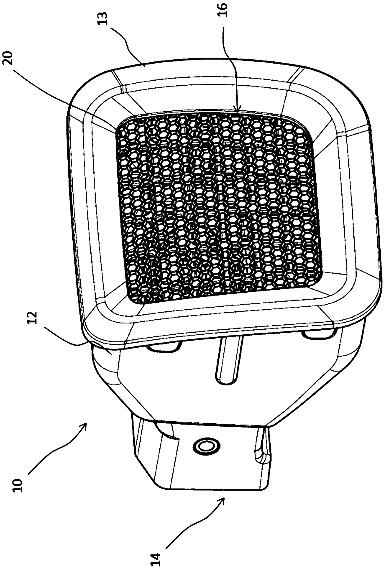
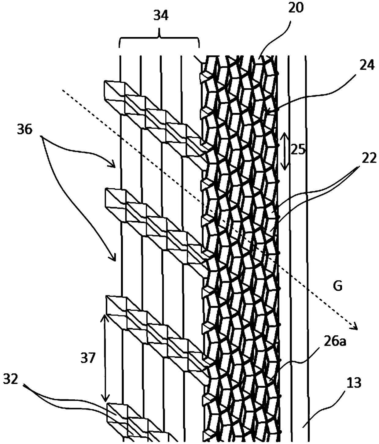
[0040] Figure 1 to Figure 3 The air vent of the present invention according to the first exemplary embodiment is shown. The vent 10 includes a housing 12 having an air duct 18 extending from an air inlet end 14 to an air outlet end 16 . At the air outlet end 16 a partition 13 is arranged, wherein the outflow grid 20 is received in the partition 13 .

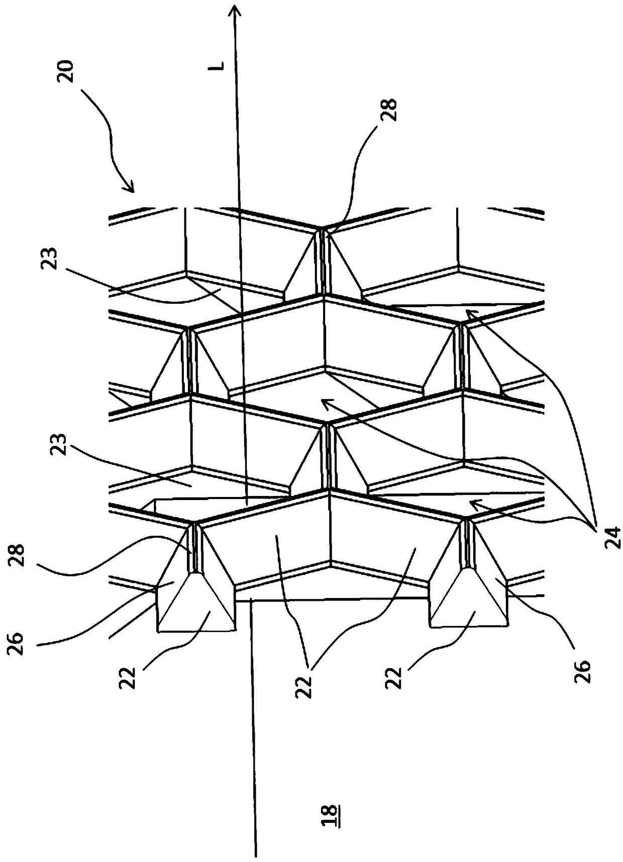
[0041] figure 2 show figure 1 A detailed view of the outflow grid 20. It can be seen here that the outflow grid 20 comprises a plurality of honeycomb grid openings 24, wherein each of the plurality of honeycomb grid openings 24 is bounded by six connecting plates 22 arranged in a regular hexagon. Each of the webs 22 separates two adjacent gate openings 24 from each other. The connecting plates 22 each have two bevels 26 , wherein the bevels 26 run at an angle to the main flow direction L. As shown in FIG. In the exemplary embodiment shown here, the web 22 thus has a substantially triangular cross-sectional area. Due to t...


PUM


Abstract

An air vent for a vehicle comprises a housing, an air duct delimited by the housing and having an air inlet end and an air outlet end, wherein an air flow flowing through the air duct can flow from the air inlet end to the air outlet end along a main flow direction, an outflow grating arranged at the air outlet end, wherein the outflow grating has an opening grid with grating openings spaced apartfrom one another by means of webs. The air vent is characterized by a plurality of air-guiding elements which are arranged in the air duct upstream of the outflow grating in the flow direction, wherein the air-guiding elements form an opening grid with grating openings which are larger than the grating openings of the outflow grating.

Description

Background technique [0001] The invention relates to a vent for a vehicle comprising: a housing; an air duct defined by the housing and having an air inlet end and an air outlet end, wherein the air flow through the air duct may follow a main flow Direction flows from the air inlet end to the air outlet end; and an outflow grid, which is arranged at the air outlet end, wherein the outflow grid has an open grid with grid openings spaced apart from each other by webs open. [0002] These vents serve to ventilate the interior of the vehicle and are arranged, for example, in the dashboard of the vehicle, so that the air flow emerging from the air outlet ends of the air ducts enters the interior of the vehicle. The outflow grid at the air outlet end of the air duct conceals the air duct behind the outflow grid when viewed from the inside of the vehicle. Furthermore, these air vents can be integrated particularly well into the surrounding components of the dashboard. Both are vis...

Claims


Application Information

Patent Timeline
Patent Type & Authority Applications(China)
IPC IPC(8): B60H1/34
CPCB60H1/3414B60H1/3421B60H1/3407B60H2001/3492B60H2001/3471
Inventor 迈克尔·德梅拉特
Owner ILLINOIS TOOL WORKS INC
Why Eureka
Try Eureka