EGR valve assembly

An EGR valve and component technology, applied in engine components, exhaust gas recirculation, machine/engine, etc., can solve problems such as damage to turbocharger compressors, interference, deterioration of internal combustion engine performance, etc., to achieve a simple structure and reduce interference. Effect

Inactive Publication Date: 2016-11-02
GM GLOBAL TECH OPERATIONS LLC
View PDF7 Cites 2 Cited by
  • Summary
  • Abstract
  • Description
  • Claims
  • Application Information

AI Technical Summary

Problems solved by technology

[0004] The intake vanes can cause disturbances in the intake air flow which can adversely deteriorate the performance of the internal combustion engine
In particular, the formation of water condensate is disadvantageously increased, which in particular damages the compressor of the turbocharger

Method used


Image

  • EGR valve assembly
  • EGR valve assembly

Examples


Embodiment Construction

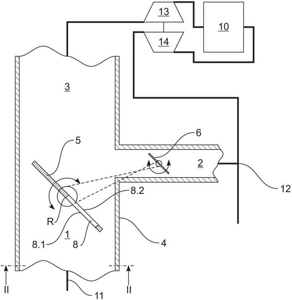
[0031] figure 1 Partially schematically shown is an internal combustion engine of a passenger car having an EGR valve assembly according to an embodiment of the present invention.

[0032] The internal combustion engine comprises a cylinder device 10, an air intake pipe 11 for supplying air to the cylinder device 10, an exhaust pipe 12 for discharging exhaust gas from the cylinder device 10, a turbocharger and an LP-EGR system, the turbo A supercharger includes a compressor 13 that compresses intake air and a turbine 14 that drives and drives the compressor 13 through exhaust gas, and the LP-EGR system includes the (LP-)EGR valve assembly.

[0033] The LP-EGR valve assembly includes an intake air passage 1 , an exhaust passage 2 and an outlet passage 3 formed in or through a common housing 4 .

[0034] The intake passage 1 communicates with the air intake pipe 11 , the exhaust passage 2 communicates with the exhaust pipe 12 downstream of the turbine 14 , and the outlet passage ...


PUM


Abstract

The invention relates to an EGR valve assembly comprising a gas intake passage (1), a gas exhaust channel (2), an outlet channel (3), a movable gas intake fin (5) for changing a free cross section of the gas intake passage (1) and a movable gas exhaust fin (6) for changing the free cross-section of the gas exhaust channel (2), wherein the gas intake fin (5) comprises at least one channel (8) connecting an inlet (8.1) in the surface of the upstream side of the fin (5) and an outlet (8.2) in the surface of the downstream side of the fin (5).

Description

technical field [0001] The present invention relates to an exhaust gas recirculation ("EGR") valve assembly, an internal combustion engine including the EGR valve assembly, and a passenger car including the same. Background technique [0002] According to internal practice, EGR systems are known in which the exhaust gas from the internal combustion engine flows back into the intake air flow of the engine. Exhaust flow is variably controlled by a movable exhaust vane disposed in an exhaust passage of the EGR valve assembly. [0003] Specifically, in order to induce a variable pressure drop in the intake air flow allowing the exhaust gas to recycle, movable intake vanes are provided in the intake passage of the EGR valve assembly. [0004] The air intake vanes can cause disturbances in the air flow of the intake air, which can adversely affect the performance of the internal combustion engine. In particular, the formation of water condensate is disadvantageously increased, w...

Claims


Application Information

Patent Timeline
Patent Type & Authority Applications(China)
IPC IPC(8): F02M26/06F02M26/13F02M26/70
CPCF02M26/70F02M26/06
Inventor J.V.B.卡尔沃J.M.D.费尔南德斯P.P.卡布雷拉J.R.S.克鲁兹J.德拉莫里纳
Owner GM GLOBAL TECH OPERATIONS LLC
Why Eureka
Try Eureka