Eureka AIR delivers breakthrough ideas for toughest innovation challenges, trusted by R&D personnel around the world.

Communication method between electric energy meter and communication module

A technology of a communication module and a communication method is applied in the field of communication between an electric energy meter and a communication module, which can solve the problems of poor adaptability, poor communication, complicated and cumbersome, etc., and achieve the effects of improving adaptability and reducing production costs.

Inactive Publication Date: 2019-02-22
NINGBO SANXING INTELLIGENT ELECTRIC
View PDF7 Cites 2 Cited by
  • Summary
  • Abstract
  • Description
  • Claims
  • Application Information

AI Technical Summary

Problems solved by technology

[0002] With the improvement of energy meter technology, the requirements for human-computer interaction are getting higher and higher, and the most critical communication part is particularly prominent. The communication module needs to communicate with the main controller in the energy meter, and the existing energy meter communication There are many types of communication modules and various types of communication protocols that can be used, but generally one communication module can only use one communication protocol to communicate with the main controller, so that when different communication modules communicate with the main controller The control program in the main controller needs to be changed, or the control program in the main controller needs to be changed when the original communication protocol is updated, and the control program of the main controller needs to be re-burned into the code to be realized. The process is complicated and cumbersome, and the cost of modification is high. Therefore, the communication performance of the existing electric energy meter and communication module is poor, and the adaptability between the two is poor.

Method used


Image

  • Communication method between electric energy meter and communication module
  • Communication method between electric energy meter and communication module
  • Communication method between electric energy meter and communication module

Examples


Embodiment Construction

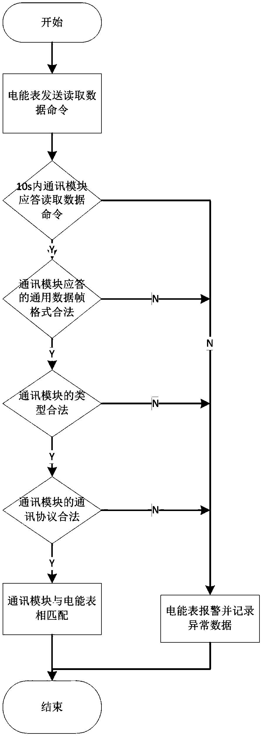
[0024] Such as figure 1 As shown, a communication method between an electric energy meter and a communication module includes the following steps:

[0025] S1. At the beginning, the type information set of the communication module and the communication protocol set of the communication module are built in the electric energy meter; the electric energy meter sends a read data command to the communication module, and the read data command is transmitted in a general data frame format;

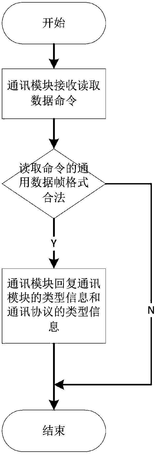
[0026] S2. The type information and communication protocol of the communication module are built in the communication module. The type information set of the communication module includes the type information of multiple communication modules, and the communication protocol set of the communication module includes the type information of multiple communication protocols; if the communication module is always If the command to read data is not answered, then enter S7; if the communication module r...


PUM


Abstract

The invention provides a communication method between an electric energy meter and a communication module. The method includes following steps: S1, a type information set of the communication module and a communication protocol set of the communication module are arranged in the electric energy meter, and the electric energy meter sends a data-reading command to the communication module; S2, if the communication module does not respond to the data-reading command, S7 is entered; and if the communication module responds, a next step is entered; S3, whether a universal data frame format responded by the communication module is legal is determined; if not, S7 is entered; and if yes, a next step is entered; S4, whether the type of the communication module is legal is determined; if not, S7 isentered; and if yes, a next step is entered; S5, whether a communication protocol of the communication module is legal is determined; if not, S7 is entered; and if yes, a next step is entered; S6, ifthe communication module is matched with the electric energy meter, S8 is entered; S7, if the communication module is not matched with the electric energy meter, the process is ended; and S8, the process is ended. According to the method, the adaptability and the universality between the communication module and the electric energy meter are improved.

Description

technical field [0001] The invention relates to the technical field of smart electric meters, in particular to a communication method between an electric energy meter and a communication module. Background technique [0002] With the improvement of energy meter technology, the requirements for human-computer interaction are getting higher and higher, and the most critical communication part is particularly prominent. The communication module needs to communicate with the main controller in the energy meter, and the existing energy meter communication There are many types of communication modules and various types of communication protocols that can be used, but generally one communication module can only use one communication protocol to communicate with the main controller, so that when different communication modules communicate with the main controller The control program in the main controller needs to be changed, or the control program in the main controller needs to be...

Claims


Application Information

Patent Timeline
IPC IPC(8): H04L29/06G01R22/06
CPCH04L69/18G01R22/063
Inventor 邢祝贺
Owner NINGBO SANXING INTELLIGENT ELECTRIC
Why Eureka
Eureka Blog
Learn More