
A remote electric meter reading device based on multi-channel digital transmission base station

A remote meter reading and multi-channel technology, which is applied in the field of electric remote meter reading devices, can solve the problems of weak signal reception, easy to be affected by the external environment, and inconvenient adjustment of signal receiving direction, and achieve the effect of reducing interference

Active Publication Date: 2021-09-24
杭州光曲智能科技有限公司
View PDF5 Cites 0 Cited by
  • Summary
  • Abstract
  • Description
  • Claims
  • Application Information

AI Technical Summary

Problems solved by technology

[0002] Automatic meter reading is a combination of computer technology, communication technology, power consumption and metering technology. It uses microelectronics and computer networks, collection, sensing, transmission and other technologies to automatically read and process meter data, and convert urban residents' water and electricity The system that comprehensively processes gas and gas information. The main object of electric meter reading is the electric meter. In order to obtain the electric meter data remotely and realize the automatic meter reading function, it is often necessary to equip the electric meter with remote and digital transmission functions. However, the existing The electric remote meter reading device based on multi-channel digital transmission base station is mainly to maintain and improve the digital transmission system, for example, the publication number is CN204117337U, and the title of the invention is "Multi-channel digital transmission base station and electric power remote meter reading system based on the base station" , which discloses a multi-channel digital transmission base station and a remote meter reading system, but the structure of the physical device is less modified, and the meter data is still easily affected by the external environment when it is transmitted, making the data The transmission is unstable, which is manifested in the fact that the receiving signal is not strong, and the direction of signal receiving is not easy to adjust, etc.

Method used


Image

  • A remote electric meter reading device based on multi-channel digital transmission base station
  • A remote electric meter reading device based on multi-channel digital transmission base station
  • A remote electric meter reading device based on multi-channel digital transmission base station

Examples


Embodiment 1

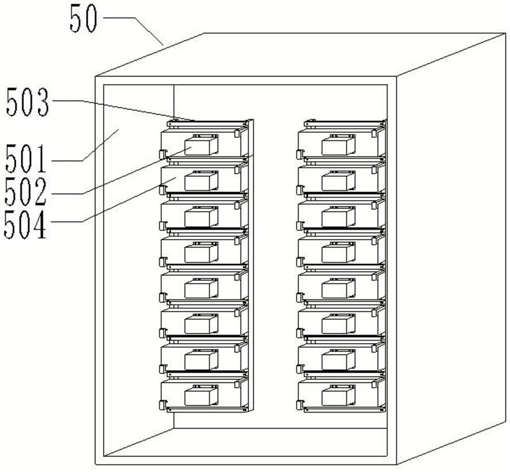
[0038] Such as figure 1 , figure 2 , image 3 and Figure 9 As shown, a power remote meter reading device based on a multi-channel digital transmission base station includes a multi-channel digital transmission base station 10, a wireless collector 20, a 230MHz wireless terminal 30, a power system data center 40 and a user meter box 50, and a 230MHz wireless terminal The working frequency of 30 is 230MHz; the wireless collector 20 is connected with the 230MHz wireless terminal 30, and is used to collect the electric meter 502 data of the user electric meter box 50 in a wireless manner, and send the collected electric meter 502 data to the 230MHz wireless terminal 30; multi-channel digital transmission The base station 10 is connected with the power system data center 40, and is used to receive the data of the electric meter 502 collected by the wireless collector 20 through the 230MHz wireless terminal 30, and send the collected data of the electric meter 502 to the electri...

Embodiment 2

[0056] Such as Figure 1-Figure 4 As shown, the difference from Embodiment 1 is that further, the driving member 5052 is set as a driving motor, the output end of the motor shaft of the driving motor is fixed to the input end of the connecting rod 5051 through a coupling, and the driving motor is fixed to the box 501 on the back wall.

Embodiment 3

[0058] Such as figure 1 , figure 2 , image 3 , Figure 5 , Figure 6 and Figure 9 As shown, the difference from Embodiment 1 and Embodiment 2 is that, furthermore, a fixed guide sleeve 5011 is welded on the rear wall of the box body 501 .

[0059] Further, the driving member 5052 is configured as a driving handle 5053 and a locking screw 5054, the driving handle 5053 is fixed on the input end of the connecting rod 5051, and the driving handle 5053 fits through the guide sleeve 5011, and the locking screw 5054 passes through the guide sleeve 5011 locks the driving handle 5053, and through the cooperation of the guide sleeve 5011, the driving handle 5053 and the locking screw 5054, the antenna on the electric meter 502 can make the wireless collector 20 collect a stronger signal, and the screw on the guide sleeve 5011 can be turned. Tighten the screw 5054 so that its end abuts against the outer wall of the driving handle 5053, thereby realizing the locking of the positio...


PUM


Abstract

The invention provides an electric power remote meter reading device based on a multi-channel digital transmission base station, including a multi-channel digital transmission base station, a wireless collector, a 230MHz wireless terminal, a power system data center and a user meter box, and the working frequency of the 230MHz wireless terminal is 230MHz ;The wireless collector is connected with the 230MHz wireless terminal, which is used to collect the meter data of the user's meter box wirelessly, and send the collected meter data to the 230MHz wireless terminal; the multi-channel data transmission base station is connected with the power system data center; the user's meter box is set In order to include the box body, the electric meter and the angle adjustment mechanism, the angle adjustment mechanism is set in the box body, the electric meter is arranged on the angle adjustment mechanism, the electric meter is connected with an antenna, and the electric meter feeds back the electric meter data to the wireless collector through the antenna. The invention adopts the meter reading device, which can adjust the angle of the electric meter in the electric meter box of the user, so as to effectively ensure a strong communication signal between the antenna on the electric meter and the wireless collector, thereby realizing stable and reliable transmission of electric meter data.

Description

technical field [0001] The invention relates to the technical field of electric remote meter reading devices, in particular to an electric remote meter reading device based on a multi-channel digital transmission base station. Background technique [0002] Automatic meter reading is a combination of computer technology, communication technology, power consumption and metering technology. It uses microelectronics and computer networks, collection, sensing, transmission and other technologies to automatically read and process meter data, and convert urban residents' water and electricity The system that comprehensively processes gas and gas information. The main object of electric meter reading is the electric meter. In order to obtain the electric meter data remotely and realize the automatic meter reading function, it is often necessary to equip the electric meter with remote and digital transmission functions. However, the existing The electric remote meter reading device b...

Claims


Application Information

Patent Timeline
Patent Type & Authority Patents(China)
IPC IPC(8): H04Q9/00G08C17/02F16M13/02F16M11/10
CPCF16M11/10F16M13/02G08C17/02H04Q9/00H04Q2209/43H04Q2209/60
Inventor 续麦贵
Owner 杭州光曲智能科技有限公司
Learn More