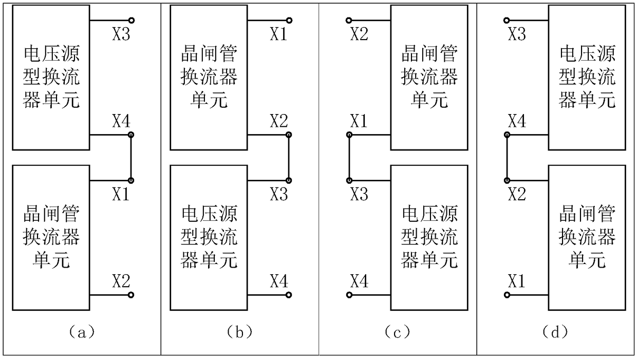
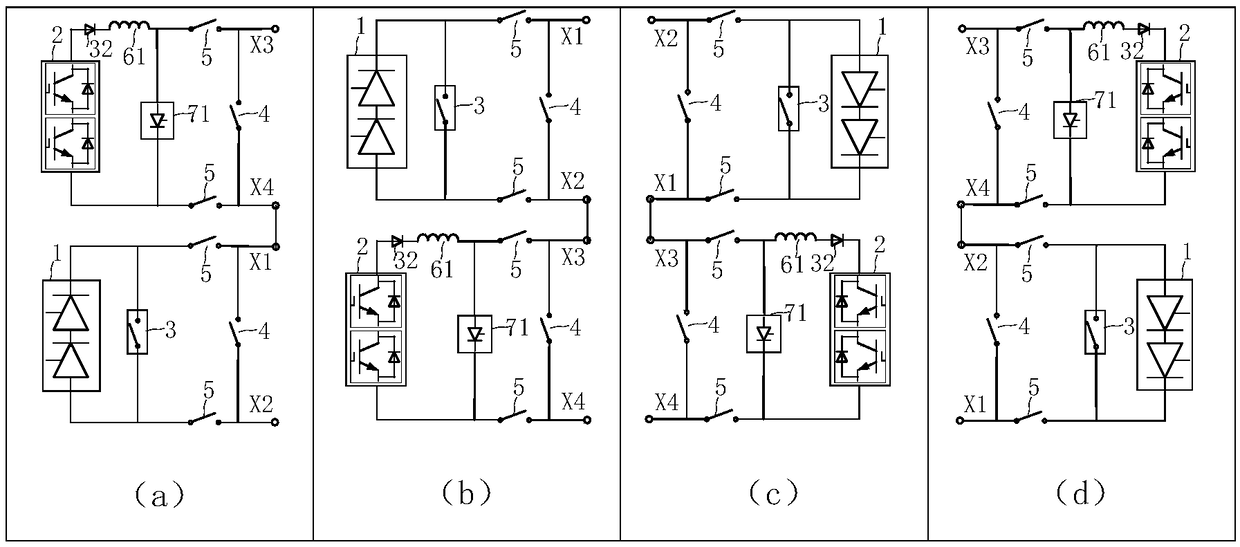
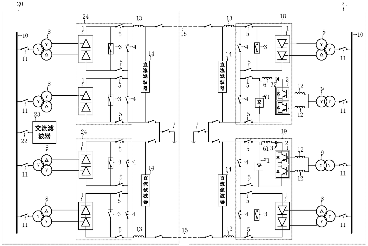
Withdrawal device and method for series converter of hybrid direct-current power transmission system
A power transmission system, hybrid DC technology, applied in the direction of circuit devices, AC network circuits, electrical components, etc., can solve the problems of lack of versatility
- Summary
- Abstract
- Description
- Claims
- Application Information
AI Technical Summary
Problems solved by technology
Method used
Image
Examples
Embodiment 1
[0120] A preferred embodiment 1 is:
[0121] The control unit performs the following steps when the discrimination unit detects that the hybrid direct current transmission system needs to perform a converter exit operation:
[0122] (1) Control the rectifier converter station to increase the firing angle, and control the DC voltage of the inverter converter station to decrease to the range that allows the converter to exit;
[0123] (2) Control the voltage source converter that needs to be exited from the inverter station to perform the following two operations, and the operation sequence of the two operations is not in particular order:
[0124] (a2) Blocking the voltage source converter that needs to be withdrawn from the inverter station;
[0125] (b2) Close the parallel bypass circuit on the DC side;
[0126] (3) To control the voltage source converter that needs to exit from the inverter station, perform the following two operations, and the operation sequence of the tw...
Embodiment 2
[0136] A preferred embodiment 2 is:
[0137] The control unit performs the following steps when the discrimination unit detects that the hybrid direct current transmission system needs to perform a converter exit operation:
[0138] (21) Control the rectifier converter station to increase the firing angle, and control the DC voltage of the inverter converter station to decrease to the range that allows the converter to exit;
[0139] (22) To control the thyristor converter that needs to be withdrawn from the rectifier station, perform the following two operations, two parts
[0140] The order of operations is in no particular order:
[0141] (a22) Close the DC side parallel bypass switch;
[0142] (b22) Thyristor converters that need to be withdrawn from the block rectification converter station;
[0143] (23) To control the thyristor converter that needs to be withdrawn from the rectifier station, perform the following two operations, two parts
[0144] The order of operati...
Embodiment 3
[0163] A preferred embodiment 3 is:
[0164] The method for exiting the converter includes the following steps:
[0165] (1) Control the rectifier converter station to increase the firing angle, and control the DC voltage of the inverter converter station to decrease to the range that allows the converter to exit;
[0166] (2) Control the voltage source converter that needs to be exited from the inverter station to perform the following two operations, and the operation sequence of the two operations is not in particular order:
[0167] (a2) Blocking the voltage source converter that needs to be withdrawn from the inverter station;
[0168] (b2) Close the parallel bypass circuit on the DC side;
[0169] (3) To control the voltage source converter that needs to exit from the inverter station, perform the following two operations, and the operation sequence of the two operations is not in particular order:
[0170] (a3) Disconnect the DC side isolation switch;
[0171] (b3) ...
PUM
 Abstract
Description
Claims
Application Information
 - R&D
- Intellectual Property
- Life Sciences
- Materials
- Tech Scout
- Unparalleled Data Quality
- Higher Quality Content
- 60% Fewer Hallucinations
Browse by: Latest US Patents, China's latest patents, Technical Efficacy Thesaurus, Application Domain, Technology Topic, Popular Technical Reports.
© 2025 PatSnap. All rights reserved.Legal|Privacy policy|Modern Slavery Act Transparency Statement|Sitemap|About US| Contact US: help@patsnap.com


