
Concrete mixing machine for building

A technology for concrete mixers and construction, which is applied in cement mixing devices, clay preparation devices, and sales of raw material supply devices, etc. It can solve problems such as high labor intensity, inconvenient use, and low work efficiency, so as to reduce labor intensity and avoid deformation. The effect of saving loading time

Inactive Publication Date: 2019-02-19
史振荣
View PDF9 Cites 0 Cited by
  • Summary
  • Abstract
  • Description
  • Claims
  • Application Information

AI Technical Summary

Problems solved by technology

[0002] In engineering construction, concrete is often used, so it is essential for mixing construction materials. At present, the batching and mixing of materials are mostly done manually or by mixers. Manual batching and mixing are suitable for small bridges and roads For large-scale projects, mechanized production equipment must be used. However, whether it is in small-scale construction or in large-scale construction, feeding materials is a labor-intensive job. The larger the capacity of the mixer, the higher the mixer. The feed port will be relatively higher, and long-time artificial high-place feeding will lead to low work efficiency. Some mixers in the existing devices all have this defect of inconvenient use. Therefore, it is necessary to improve the prior art to solve the above problems

Method used


Image

  • Concrete mixing machine for building
  • Concrete mixing machine for building
  • Concrete mixing machine for building

Examples


Embodiment Construction

[0020] The following will clearly and completely describe the technical solutions in the embodiments of the present invention with reference to the accompanying drawings in the embodiments of the present invention. Obviously, the described embodiments are only some, not all, embodiments of the present invention.

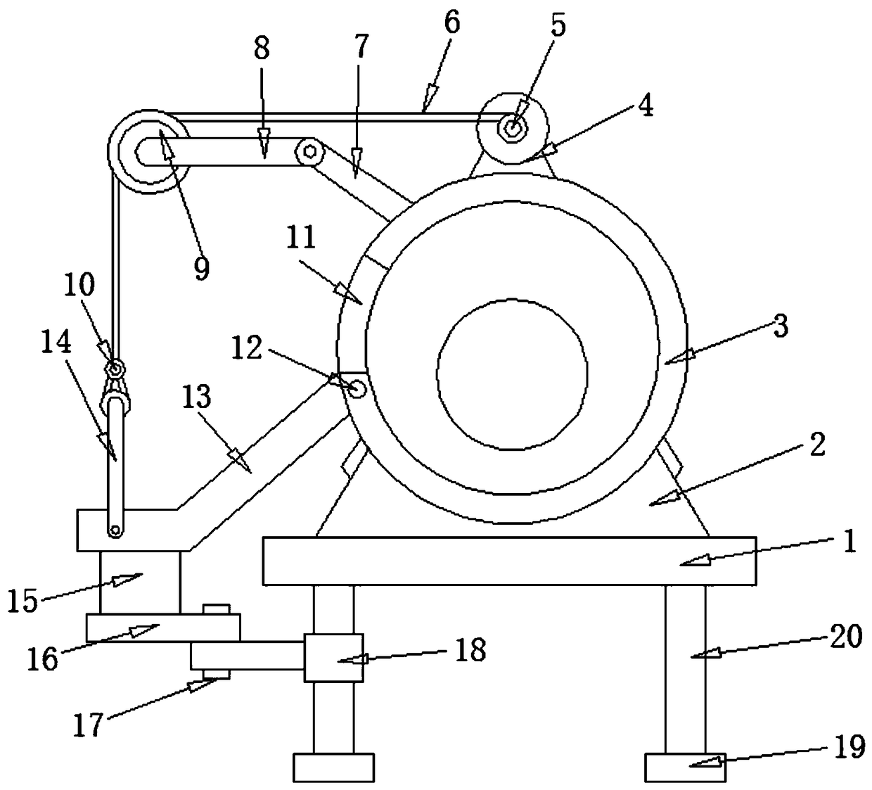
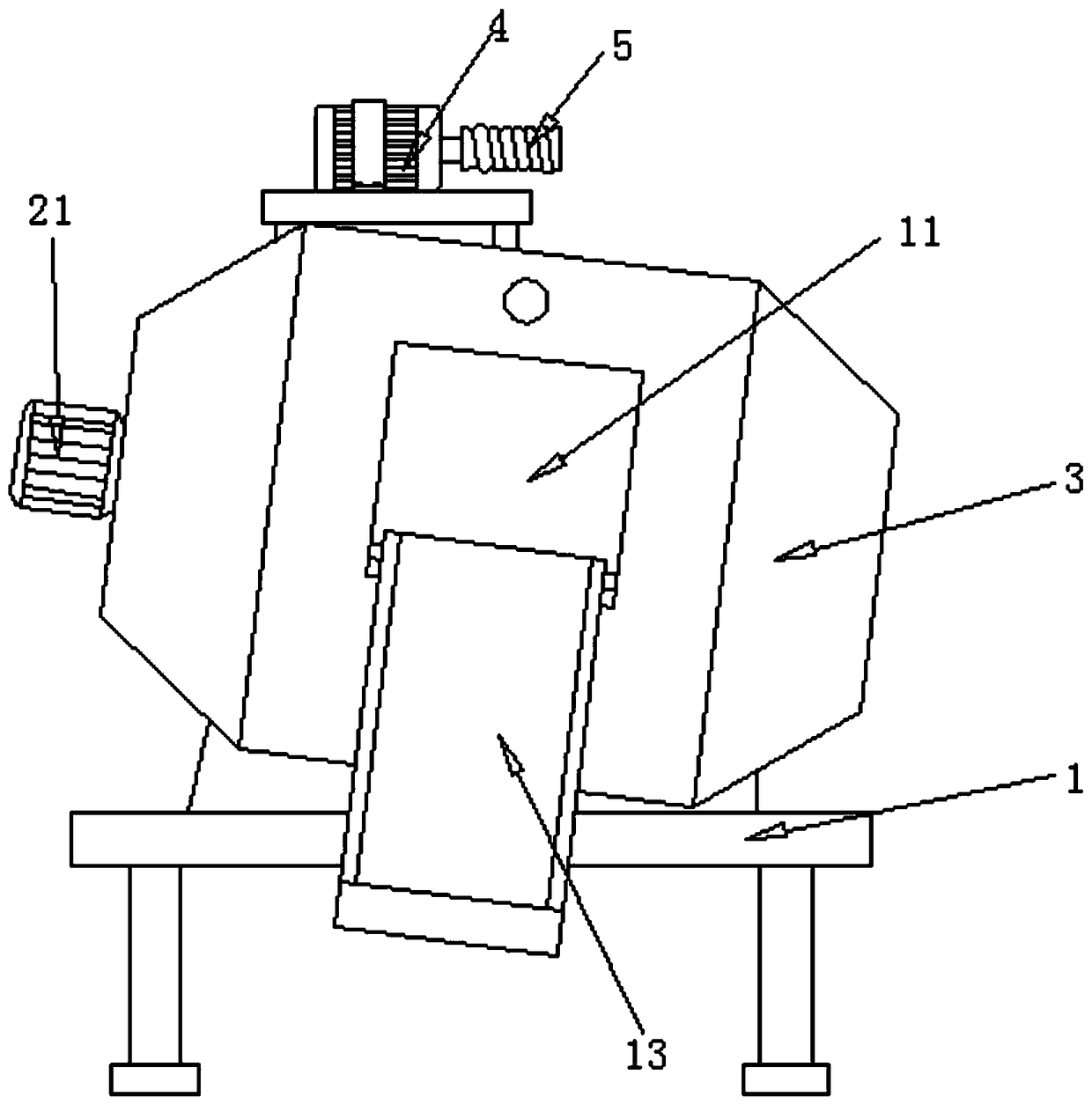
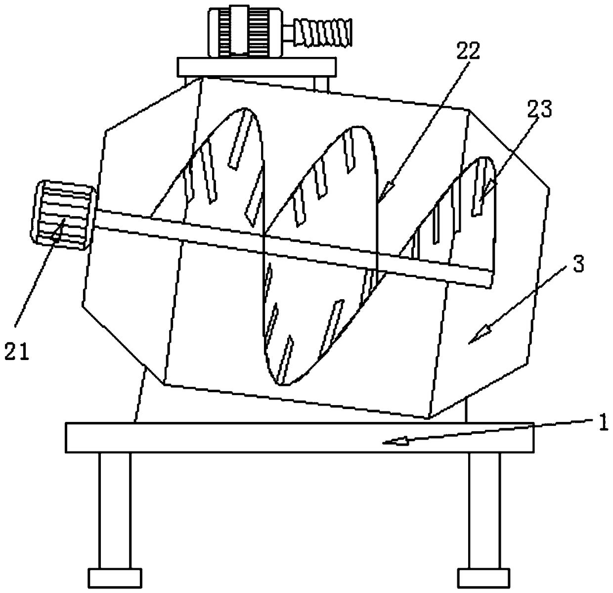
[0021] refer to Figure 1-3 , a concrete mixer for construction, comprising a mounting plate 1, four vertically placed support legs 20 are welded to the bottom outer wall of the mounting plate 1, and load-bearing blocks 19 are welded to the bottom outer walls of the support legs 20 to lower the center of gravity of the device and increase The contact area between the device and the ground improves the stability of the device. The outer wall of the top of the mounting plate 1 is welded with the mounting seat 2, and the outer wall of the top of the mounting seat 2 is fixed with the mixing tank body 3 by bolts, and the outer wall of the mixing tank body 3 has a feeding ...


PUM


Abstract

The invention discloses a concrete mixing machine for building. The concrete mixing machine comprises an installation plate, four vertically-placed supporting legs are welded to the outer wall of thebottom of the installation plate, bearing blocks are welded to the outer walls of the bottoms of the supporting legs, an installation base is welded to the outer wall of the top of the installation plate, a mixing tank body is fixed to the outer wall of the top of the installation base through a bolt, the outer wall on one side of the mixing tank body is provided with a feed inlet, a rotating shaft is inserted and connected to the inner wall of one side of the feed inlet, a guide plate is welded to the outer wall of one side of the rotating shaft, the guide plate is a bent plate, and a protection frame is welded to the outer wall of one side of the guide plate. By means of the bent guide plate, the feeding height is reduced, a worker does not need to throw raw materials into the device from a high place, the labor intensity is reduced, feeding time is saved, a winding roller stretches and retracts a pull lock, therefore, the guide plate is driven to move up and down, the raw materialsslide into the device, and device feeding convenience is improved.

Description

technical field [0001] The invention relates to the technical field of mixers, in particular to a concrete mixer for construction. Background technique [0002] In engineering construction, concrete is often used, so it is essential for mixing construction materials. At present, the batching and mixing of materials are mostly done manually or by mixers. Manual batching and mixing are suitable for small bridges and roads For large-scale projects, mechanized production equipment must be used. However, whether it is in small-scale construction or in large-scale construction, feeding materials is a labor-intensive job. The larger the capacity of the mixer, the higher the mixer. The feed port will be relatively higher, and long-time artificial high-place feeding will lead to low work efficiency. Some mixers in the existing devices all have this defect of inconvenient use. Therefore, it is necessary to improve the prior art to Solve the above problems. Contents of the invention...

Claims


Application Information

Patent Timeline
Patent Type & Authority Applications(China)
IPC IPC(8): B28C5/14B28C7/06
CPCB28C5/142B28C7/06
Inventor 史振荣吕磊张睿
Owner 史振荣
Learn More