
Disposable safe self-destroying injector with self-locked needle seat

A disposable, syringe technology, applied in the direction of syringes, hypodermic injection devices, infusion sets, etc., can solve the problems of liquid medicine and syringe loss, self-destruction, difficulty in installing the core rod, etc., and achieve the effect of convenient and quick installation

Pending Publication Date: 2019-02-19
LUOHE SHUGUANG HUIZHIKANG BIOTECH
View PDF0 Cites 5 Cited by
  • Summary
  • Abstract
  • Description
  • Claims
  • Application Information

AI Technical Summary

Problems solved by technology

[0004] The locking and self-destructing structure of the core rod and the needle cylinder has the following disadvantages: 1. Because the core rod is a rear-mounted structure, the setting of the upper and lower locking protrusions will bring difficulties to the installation of the core rod, and it must be assembled with the help of a The assembly allows the head of the mandrel to pass through the upper and lower locking protrusions and enter the interior of the syringe; 2. Once the drawing is too large during the pumping process, the engaging protrusion on the mandrel will pass over the upper locking protrusion And lead to premature self-destruction, resulting in unnecessary loss of liquid medicine and syringes

Method used


Image

  • Disposable safe self-destroying injector with self-locked needle seat
  • Disposable safe self-destroying injector with self-locked needle seat
  • Disposable safe self-destroying injector with self-locked needle seat

Examples


Embodiment Construction

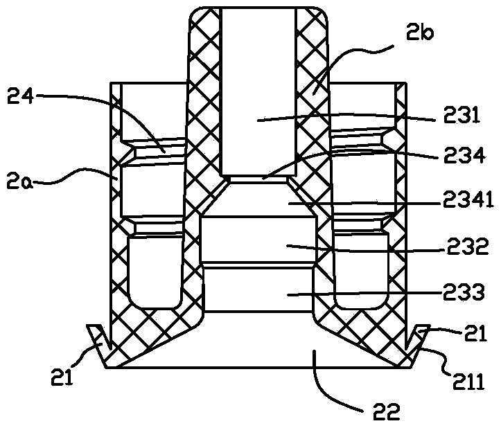
[0035] Such as figure 1 As shown, a disposable safe self-destructing syringe with self-locking needle seat includes a syringe 1, a needle seat 2 and a core rod 3. Installed in the inner hole 11 of the syringe 1.

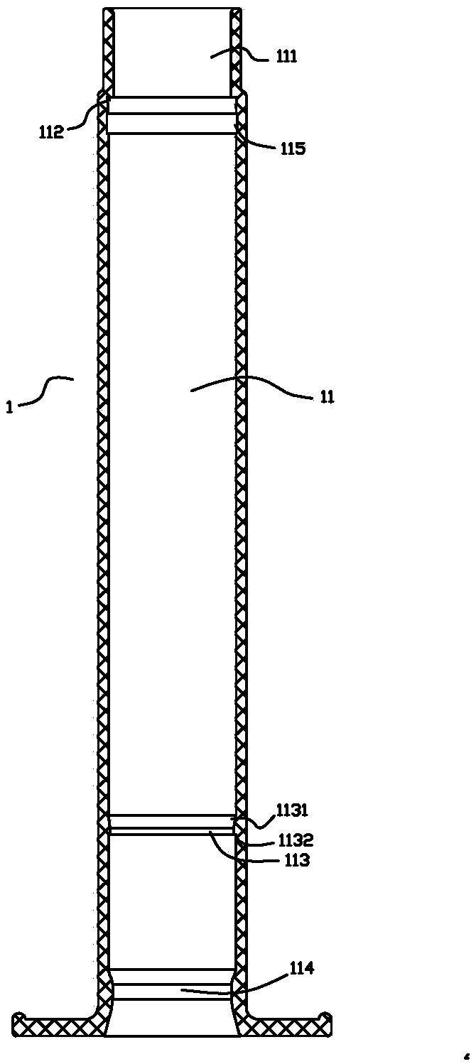
[0036] Such as figure 2 As shown, the upper mouth of the inner hole 11 of the syringe is provided with a mounting hole segment 111 , the inner diameter of the mounting hole segment 111 is smaller than the inner diameter of the inner hole 11 , and an annular stop groove 112 is provided below the mounting hole segment 111 . The lower part of the inner hole 11 of the syringe is provided with a locking structure composed of an upper locking protrusion 113 and a lower locking protrusion 114 , the inner diameter of the upper locking protrusion 113 is larger than the inner diameter of the lower locking protrusion 114 . An inclined plane 1131 is arranged between the upper side of the upper locking protrusion 113 and the inner hole wall of the syringe, and a right-angled s...


PUM


Abstract

The invention discloses a disposable safe self-destroying injector with a self-locked needle seat. The disposable safe self-destroying injector comprises a needle tube, the needle seat and a core bar,wherein a mounting hole section is arranged at an upper opening portion of an inner hole of the needle tube; an annular stop slot is arranged below the mounting hole section; the bottom of the outerwall of the needle seat is provided with a plurality of inverted stop claws or elastic sheets distributed along a circumferential direction in a spacing manner; the tops of the various stop claws or elastic sheets are abutted with the top surface of the annular stop slot; a check ring made of an elastic material is arranged below the needle seat; the outer wall of the check ring is hermetically located on the wall of the inner hole of the needle tube; the lower part of the inner hole of the needle tube is provided with a locking structure composed of an upper locking protrusion and a lower locking protrusion; and the stop claws or elastic sheets on the needle seat can cross over the upper locking protrusion to realize upper locking and stopping after the needle seat is backwards pulled bythe core bar in place. According to the disposable safe self-destroying injector with the self-locked needle seat, the needle seat with a locating tip is redesigned; locking during self destroying isrealized by means of the needle seat, which brings great convenience to the installation of the core bar; and meanwhile, early self-destroying phenomenon of the injector can be effectively avoided.

Description

technical field [0001] The invention relates to a disposable safety self-destruction syringe, in particular to a disposable safety self-destruction syringe with self-locking needle seat. Background technique [0002] In the modern medical process, the syringe is the most commonly used device for doctors. In order to avoid safety and medical risks such as cross-infection, the existing syringes adopt a one-time self-destruct structure, that is, the syringe is self-destructed after use. Cannot be reused twice. [0003] At present, there are many types of self-destructing syringes on the market. Among them, the self-destructing structure of one type of syringe is realized by manually pulling the push rod back. There is a locking protrusion on the outer wall of the rod head. Once the core rod is pulled back, the locking protrusion crosses the upper locking protrusion and enters the locking groove to realize the locking of the core rod. At this time, the core rod cannot move forw...

Claims


Application Information

Patent Timeline
IPC IPC(8): A61M5/178A61M5/31A61M5/50
CPCA61M5/178A61M5/31A61M5/5086
Inventor 万鹏
Owner LUOHE SHUGUANG HUIZHIKANG BIOTECH
Learn More