A method for replacing insulation piercing wire clips with special-shaped and hooking wire clips under load

An insulation piercing and load-bearing technology, applied in the direction of overhead lines/cable equipment, etc., can solve the problems of long-term power failure and economic loss of users, and achieve the effect of improving conductivity, increasing contact area, and shortening maintenance time.

Active Publication Date: 2020-07-28
NANCHONG POWER SUPPLY COMPANY STATE GRID SICHUANELECTRIC POWER
View PDF7 Cites 0 Cited by
  • Summary
  • Abstract
  • Description
  • Claims
  • Application Information

AI Technical Summary

Problems solved by technology

[0003] What the present invention is to solve is to replace the insulating puncture wire clip in the prior art by means of a power outage of the main network wire or live replacement when the user's T-connected drain line is under no load. These two methods will cause a long-term power outage for the user, resulting The technical problem of huge economic loss is to provide a method for replacing the insulation piercing clamp with a load to a special-shaped and hooking clamp

Method used


Image

  • A method for replacing insulation piercing wire clips with special-shaped and hooking wire clips under load
  • A method for replacing insulation piercing wire clips with special-shaped and hooking wire clips under load
  • A method for replacing insulation piercing wire clips with special-shaped and hooking wire clips under load

Examples


Embodiment

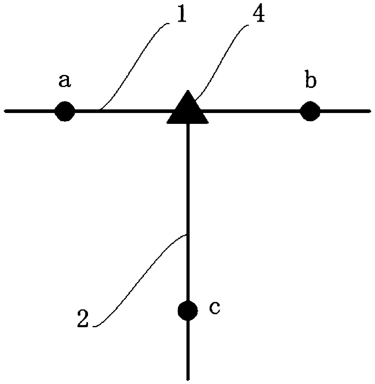
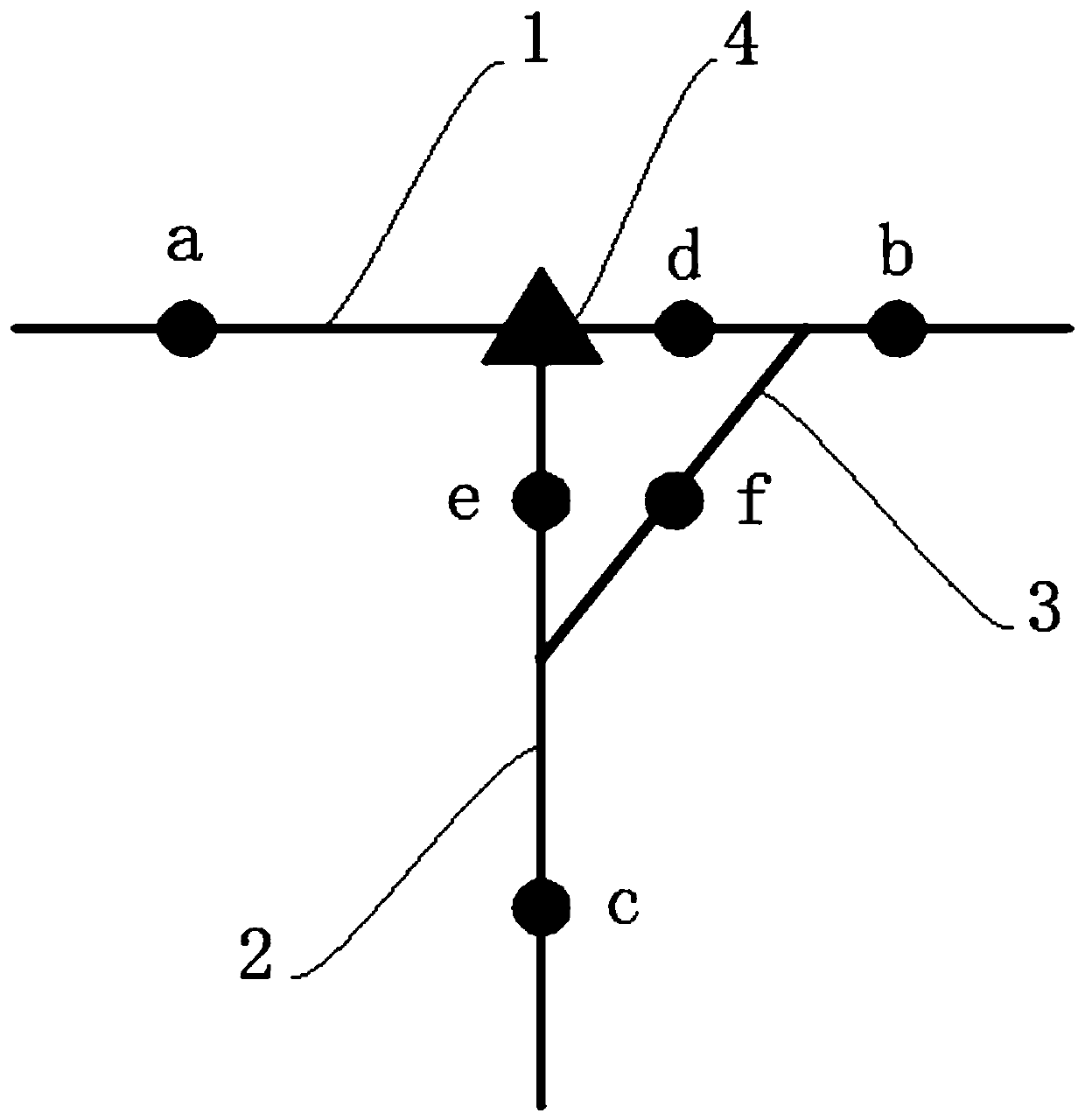
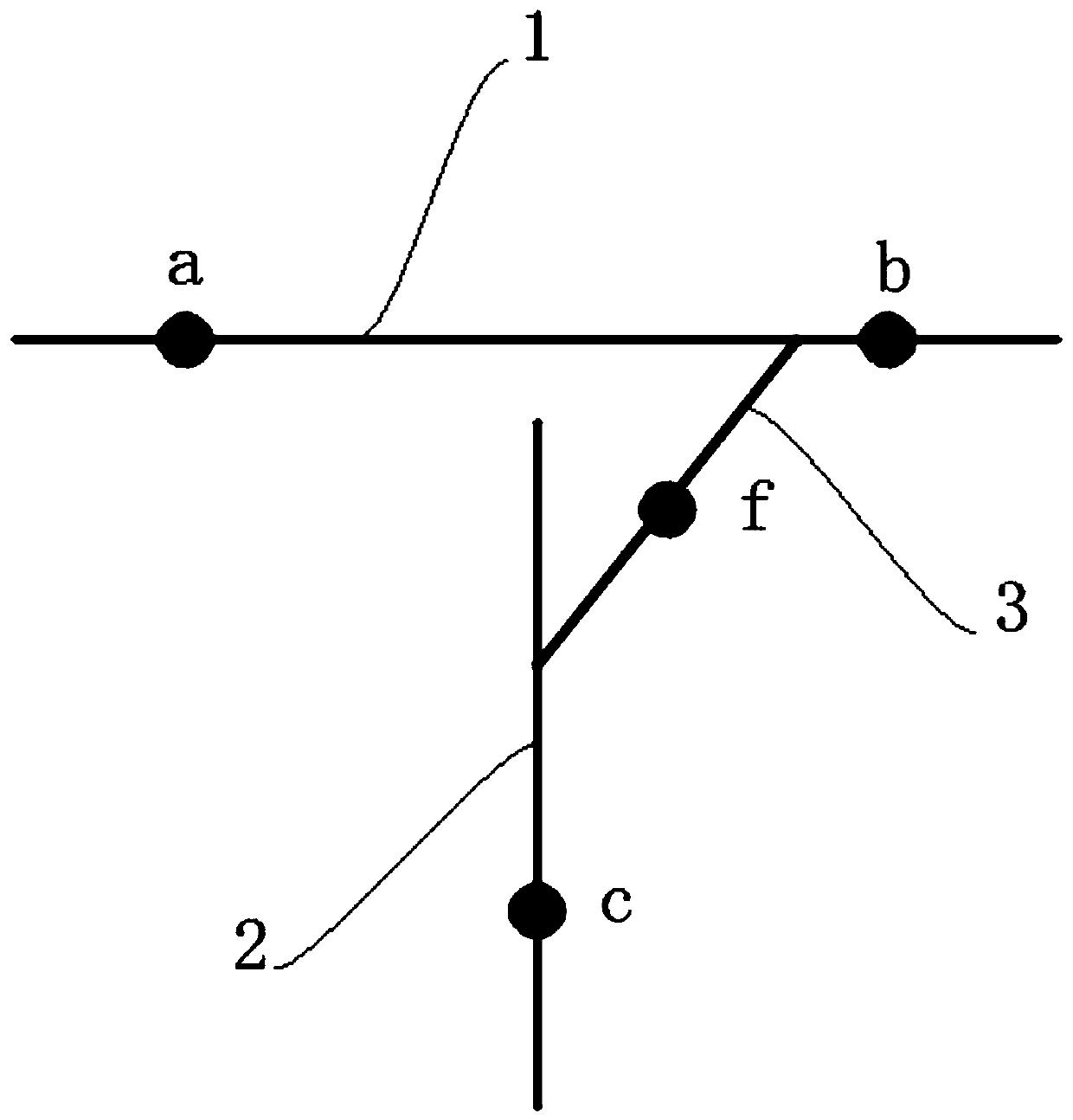
[0026] Such as Figure 1 to Figure 4 As shown, a method for replacing the insulating puncture wire clamp with load into a special-shaped and hooked wire clamp of the present invention includes the following steps:

[0027] Step 1: Use a digital multimeter to actually measure the current at points a and b of the main network wire 1 and the current at point c of the user T-connected drain wire 2 and record them. The current at point b of the main network wire 1 is used for reference verification; Whether the current-carrying capacity of the diversion line 3 meets the user's load requirements, the current-carrying capacity of the bypass diversion line 3 is selected according to the fact that the current at point a of the main network conductor 1 is greater than twice the current at the point c of the user T connected with the diversion line 2 , after determining the ampacity of the bypass drain line 3, determine the wire diameter of the bypass drain line 3 according to the ampaci...


PUM


Abstract

The invention discloses an on-load method for changing an insulation piercing clamp into an irregularly-shaped jumper hooking cable clamp. The method comprises the following steps: actually measuringmain grid wire current and user T-side drainage wire current by using a digital multimeter, and determining the carrying capacity of a bypass drainage wire meets the requirement of user load; connecting a user T-side drainage with a main grid wire by using the bypass drainage wire, actually measuring the bypass drainage wire current, the user T-side drainage wire current, the incoming side currentof the main grid wire and the receiving side current of the main grid wire, after the current of each measured point location is examined to be normal, taking off the piercing clamp, connected with the main grid wire, of the user T-side drainage wire, using the irregularly-shaped jumper hooking cable clamp with matched model for connection; then actually measuring the bypass drainage wire current, the user T-side drainage wire current, the incoming side current of the main grid wire and the receiving side current of the main grid wire again, and dismantling the bypass drainage wire. Accordingto the method, the insulation piercing clamp is changed into the irregularly-shaped jumper hooking cable clamp in an on-load manner under the condition that the user electricity is not influenced, sothat the inconvenience of power failure for users is avoided.

Description

technical field [0001] The invention relates to the technical field of electric power construction, in particular to a method for replacing an insulating puncture wire clip with a load and hooking the wire clip into a special shape. Background technique [0002] Insulation piercing clamps are often used to connect traditional user T-connection lines to main network lines. However, due to the uneven quality of insulation piercing clamps and the long service life, it is easy to oxidize and age, making the operation and maintenance of power transmission and distribution lines difficult. It is very inconvenient and prone to tripping faults in urban lines due to insulation piercing clips. Without affecting the safe and stable operation of the power grid, what method to use to replace the insulation piercing clamp has become an urgent problem to be solved. The traditional solution is mainly to replace the main network conductors in the form of a power outage or live replacement w...

Claims


Application Information

Patent Timeline
Patent Type & Authority Patents(China)
IPC IPC(8): H02G1/02
CPCH02G1/02
Inventor 赵廷刚徐凯波邹庆费强张彪刘朋赵冲
Owner NANCHONG POWER SUPPLY COMPANY STATE GRID SICHUANELECTRIC POWER
Why Eureka
Try Eureka