
Bottom binding post assembly device and electric leakage switch production equipment

A technology for assembling devices and terminals, which is applied in the manufacture of electrical switches, emergency protection devices, and emergency protection devices, etc., can solve the problems of easy loosening of workpieces, low precision, error-prone, low precision, etc., so as to reduce defective products, solve the problems of handling and Assembly process, high precision effect

Inactive Publication Date: 2019-02-15
练国瑛
View PDF3 Cites 0 Cited by
  • Summary
  • Abstract
  • Description
  • Claims
  • Application Information

AI Technical Summary

Problems solved by technology

Most of the existing production methods are done manually, and there are also some equipment assembly, but it cannot cover the automatic and efficient assembly of all components
[0003] The shortcomings of the existing equipment are: 1. Low degree of automation and low pass rate of finished products; 2. Unable to accurately complete the loading of various small components of the leakage switch, and the handling accuracy is low, resulting in low processing efficiency and finished product pass rate; 3. It is difficult to fasten the two plastic sheets, the precision of step-by-step assembly is low and error-prone, the assembly accuracy and product qualification rate are low; 4. Changing the posture of the terminal during assembly causes large assembly errors; 5. It is difficult to assemble the bottom terminal from bottom to top Low precision, resulting in low processing efficiency and finished product pass rate; 6. Low handling accuracy of the bottom lug 600, resulting in low assembly accuracy and product pass rate; 7. The workpiece is easy to loose in the carrier, and the carrier is not rigid when it is in circulation , resulting in a low success rate of assembly

Method used


Image

  • Bottom binding post assembly device and electric leakage switch production equipment
  • Bottom binding post assembly device and electric leakage switch production equipment
  • Bottom binding post assembly device and electric leakage switch production equipment

Examples


Embodiment Construction

[0021] The present invention will be further described below in conjunction with the accompanying drawings and embodiments.

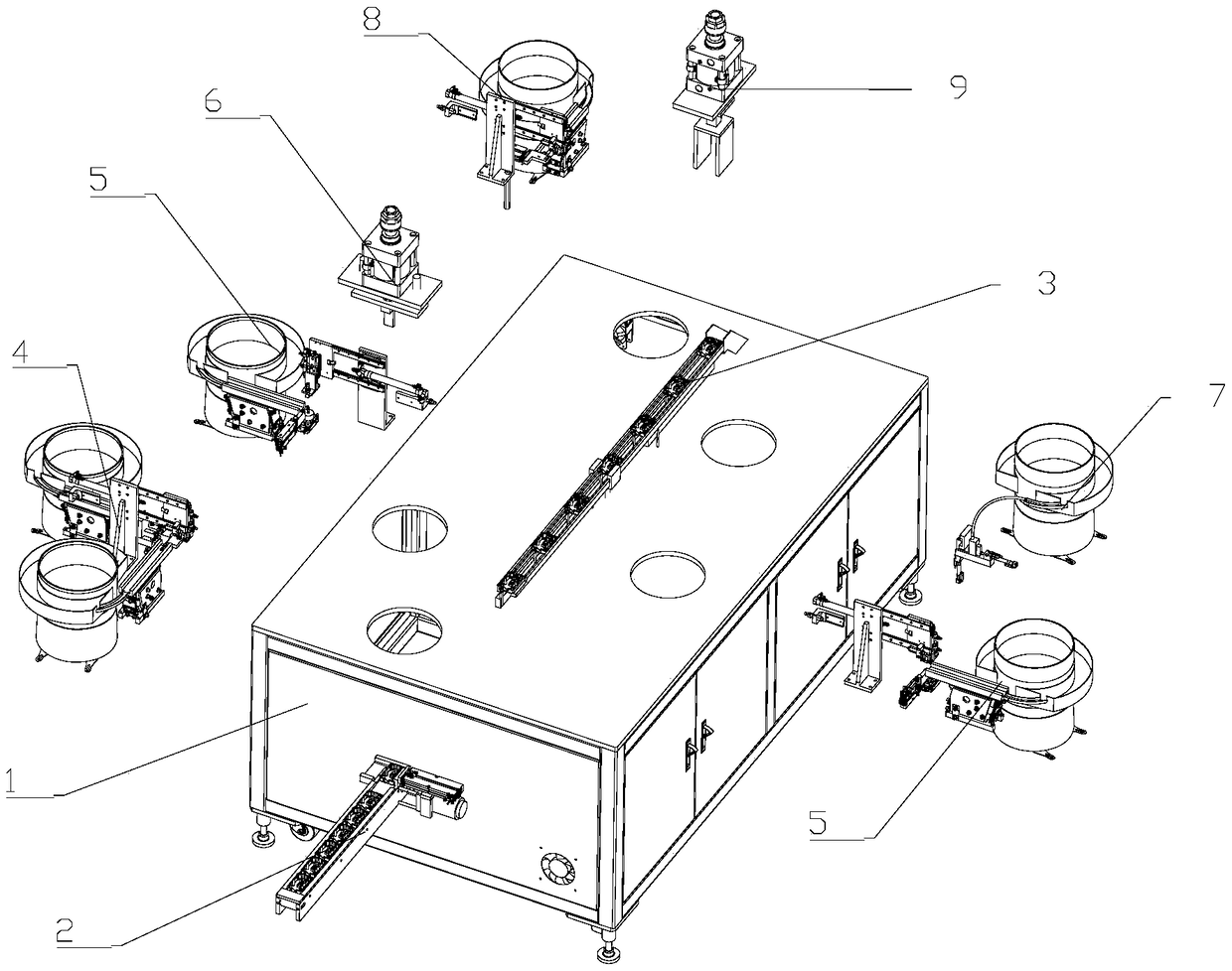
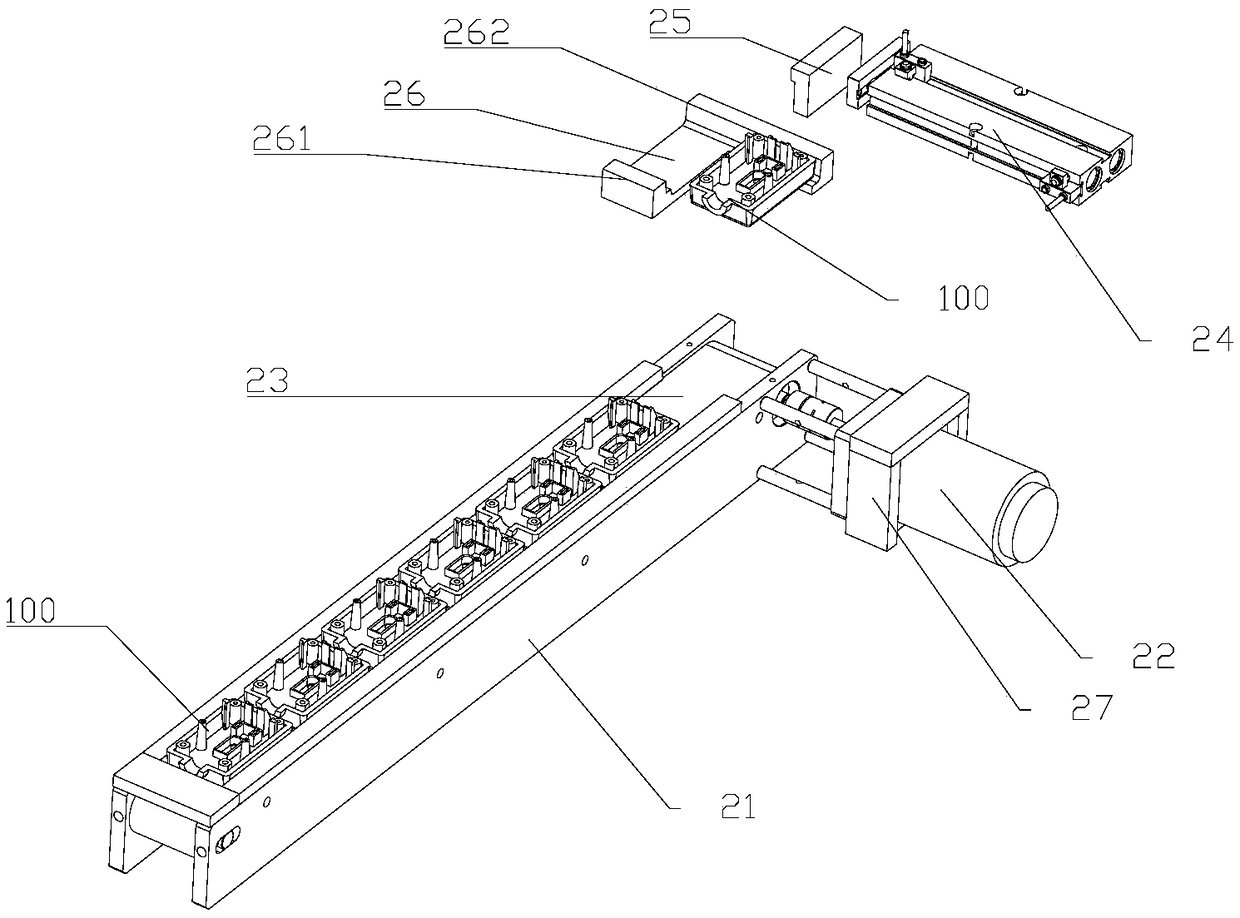
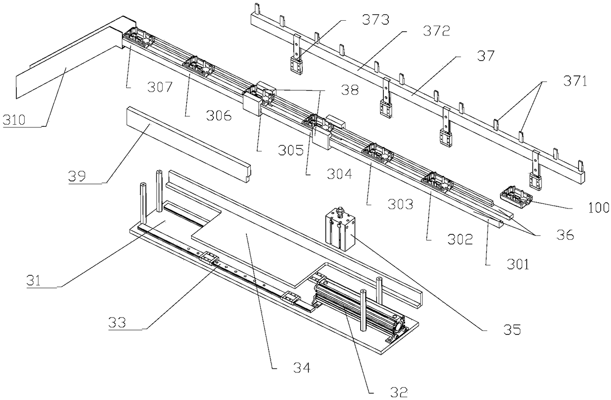
[0022] Such as figure 1 The leakage switch production equipment shown includes a frame 1 and a feeding device 2 installed on the frame 1, a multi-station circulation device 3, a plastic part assembly device 4, a terminal post assembly device 5, a pressing device 6, a bottom Terminal assembly device 7 , bottom lug assembly device 8 and riveting device 9 . Along the processing direction of the workpiece, the plastic parts assembly device 4, the terminal assembly device 5, the pressing device 6, the bottom terminal assembly device 7, the bottom lug assembly device 8 and the riveting device 9 are sequentially arranged, and the plastic parts assembly device 4, The position of the terminal assembly device 5 , the pressing device 6 , the bottom terminal assembly device 7 , the bottom lug assembly device 8 and the riveting device 9 corresponds to the multi-sta...


PUM


Abstract

The invention relates to the field of intelligent manufacturing of a circuit element. A bottom binding post assembly device comprises a round vibrator, a rubber pipe, a guide seat, a base, an eighth air cylinder, a ninth air cylinder, a collecting block and a jacking pin, wherein the round vibrator is used for shaking off a bottom binding post; one end of the rubber pipe is connected with a discharging opening of the round vibrator; and the other end of the rubber pipe is connected with the guide seat. The bottom binding post assembly device has the advantages that the assembly of the bottom binding post is convenient, and the assembly precision is high.

Description

technical field [0001] The invention relates to the field of intelligent manufacturing of circuit elements, in particular to the field of leakage switch production equipment. Background technique [0002] Leakage switch is a kind of switch, which is mainly used to prevent leakage accidents. There are various types of leakage switches on the market. The structure of the leakage switch includes a housing, two plastic parts, two binding posts, a bottom binding post and a bottom lug, consisting of seven components. The existing production methods are mostly done manually, and there are also some equipment assembly, but it cannot cover the automatic and efficient assembly of all components. [0003] The shortcomings of the existing equipment are: 1. Low degree of automation and low pass rate of finished products; 2. Unable to accurately complete the loading of various small components of the leakage switch, and the handling accuracy is low, resulting in low processing efficiency...

Claims


Application Information

Patent Timeline
Patent Type & Authority Applications(China)
IPC IPC(8): H01H11/00H01H69/00
CPCH01H11/00H01H69/00
Inventor 练国瑛
Owner 练国瑛
Learn More