Circulating bucket lifting discharging device of roller press

A technology of roller press and discharging machine, which is applied in the direction of conveyors, conveyor objects, transportation and packaging, etc. It can solve the problems of easy leakage of materials, achieve high installation stability, convenient loading and unloading, and easy removal.

Pending Publication Date: 2019-02-15
福建福清万年青水泥有限公司
View PDF1 Cites 1 Cited by
  • Summary
  • Abstract
  • Description
  • Claims
  • Application Information

AI Technical Summary

Problems solved by technology

[0004] However, the discharge mechanism of the bucket elevator in this utility model patent has the problem of easy material leakage on both sides when discharging.

Method used


Image

  • Circulating bucket lifting discharging device of roller press
  • Circulating bucket lifting discharging device of roller press
  • Circulating bucket lifting discharging device of roller press

Examples


Embodiment Construction

[0022] The following descriptions are only preferred embodiments of the present invention, and do not limit the scope of the present invention.

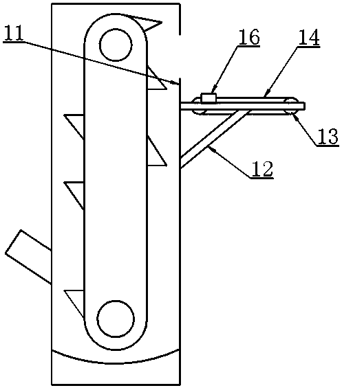
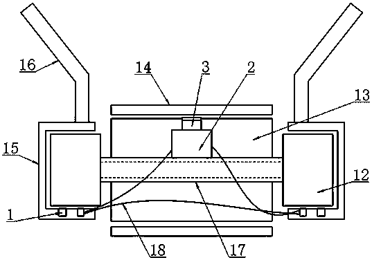
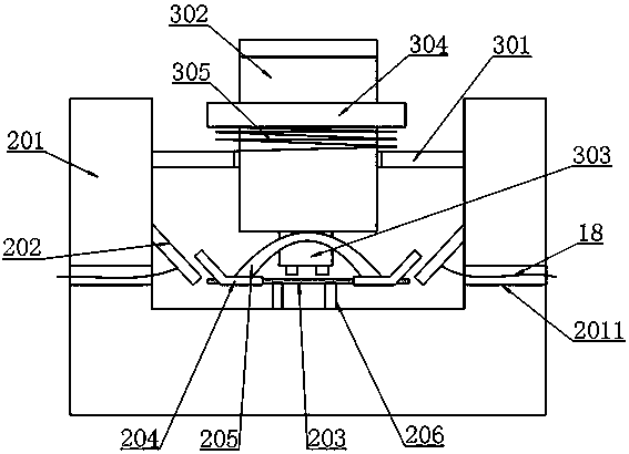
[0023] Example: as attached figure 1 , 2 , 3, 4 and attached Figure 5 As shown, a rolling bucket lifting device of a roller press includes a discharge frame 12 arranged at the position of the discharge opening 11 of the circulation bucket, pulleys 13 arranged at the positions on both sides of the discharge frame 12, and The conveying belt 14 wound on the two pulleys 13 also includes two U-shaped frames 15 respectively engaged and arranged on both sides of the discharge frame 12, and are arranged on the U-shaped frames 15 And the inclined baffle plate 16 that is used to guide the flow and discharge in the middle of the conveyor belt 14 is arranged on the inner bottom surface of the U-shaped frame 15 and is used for the electromagnetic force fixed on the discharge frame 12 by magnetic attraction. Iron unit 1, the installation beam ...


PUM


Abstract

The invention belongs to the technical field of cement production, and particularly relates to a circulating bucket lifting discharging device of a roller press. The effective discharging effect is achieved through the mode that a discharging rack, a belt pulley, a conveying belt, a U-shaped frame, an oblique baffle, an electromagnet unit, a mounting beam, a disconnecting conductive unit, a shifting power supply unit and a connecting conductor are arranged at a circulating bucket lifting discharging opening; and the circulating bucket lifting discharging device has the advantages that during belt conveying, a blocking and leakage-proof structure is reasonable and effective, the oblique baffle is rapid and convenient to mount and dismount, the mounting stability is high, in the conveying process, magnetic attraction is fixed, power is disconnected when not conveying, the oblique baffle is convenient to take down, during overall using, the power is saved, and flexibility is achieved.

Description

technical field [0001] The invention belongs to the technical field of cement production, and in particular relates to a rolling bucket lifting device of a roller press. Background technique [0002] In the cement production process, it is necessary to carry out the rolling lifting operation of the raw materials. After rolling the low-level raw materials, they are lifted by the bucket elevator, and the materials are poured into the next step after being discharged. This requires the use of a bucket with a conveying and discharging structure. pick up. But on the other hand, most of the circulating bucket feeding devices currently on the market are just ordinary conveyor belts, so there is a problem of easy material leakage on both sides, and the outlet of the bucket elevator is above the machine, so leakage The material problem is even more dangerous, and it is easy to cause the problem of smashing and injuring the staff. [0003] The patent announcement number is CN2080223...

Claims


Application Information

Patent Timeline
Patent Type & Authority Applications(China)
IPC IPC(8): B65G17/12B65G47/58B65G23/04B65G21/20
CPCB65G17/126B65G21/20B65G23/04B65G47/58
Inventor 蒋云义
Owner 福建福清万年青水泥有限公司
Why Eureka
Try Eureka