Eureka AIR delivers breakthrough ideas for toughest innovation challenges, trusted by R&D personnel around the world.

Method and device for calibrating optical module receiving end optical power, and readable storage medium

A calibration method and optical power technology, applied in electromagnetic wave transmission systems, electrical components, transmission systems, etc., can solve problems such as large errors between optical power values ​​and incident optical power

Inactive Publication Date: 2019-02-12
APAT OPTOELECTRONICS COMPONENTS
View PDF3 Cites 13 Cited by
  • Summary
  • Abstract
  • Description
  • Claims
  • Application Information

AI Technical Summary

Problems solved by technology

[0003] The main purpose of the present invention is to provide a method, device and readable storage medium for calibrating the optical power at the receiving end of an optical module, aiming to solve the technical problem of large error between the optical power value at the receiving end of the optical module and the input optical power in the prior art

Method used


Image

  • Method and device for calibrating optical module receiving end optical power, and readable storage medium
  • Method and device for calibrating optical module receiving end optical power, and readable storage medium
  • Method and device for calibrating optical module receiving end optical power, and readable storage medium

Examples


no. 1 example

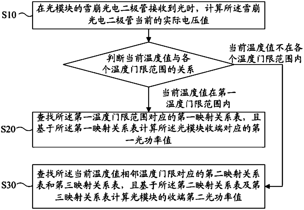
[0102] Based on the first embodiment, the third embodiment of the method for calibrating the receiving end optical power of the optical module of the present invention is proposed, please refer to Figure 4 , step S30 includes:

[0103] Step S31, calculating the first correction point based on the second mapping relationship table;

[0104] Step S32, calculating the second correction point based on the third mapping relationship table;

[0105] Step S33, calculating the second optical power value based on the first calibration point and the second calibration point.

[0106] In this embodiment, when the current temperature value is not within the range of each temperature threshold, the second mapping table and the third mapping table corresponding to the current temperature value adjacent to the temperature threshold are searched, and the first mapping table is calculated based on the second mapping table. a correction point; calculating a second correction point based on t...


PUM


Abstract

The invention discloses a method and device for calibrating optical module receiving end optical power, and a readable storage medium. The method for calibrating the optical module receiving end optical power comprises the following steps: calculating a current actual voltage value of an avalanche photodiode when the avalanche photodiode of an optical module receives a light, and judging the relationship between the current temperature value and each temperature threshold range; calculating a first optical power value corresponding to the optical module receiving end according to a first mapping relationship table if the current temperature value is within a first temperature threshold range of each temperature threshold range; and calculating a second optical power value of the optical module receiving end based on a second mapping relationship table and a third mapping relationship table if the current temperature value is not within each temperature threshold. Both the difference between the first optical power value in the invention and the incoming optical power corresponding to the light and the difference between the second optical power value in the invention and the incoming optical power corresponding to the light are small; therefore, the error between the incoming optical power and the received optical power is effectively reduced, and high-precision requirements for optical power reported by the receiving end are realized.

Description

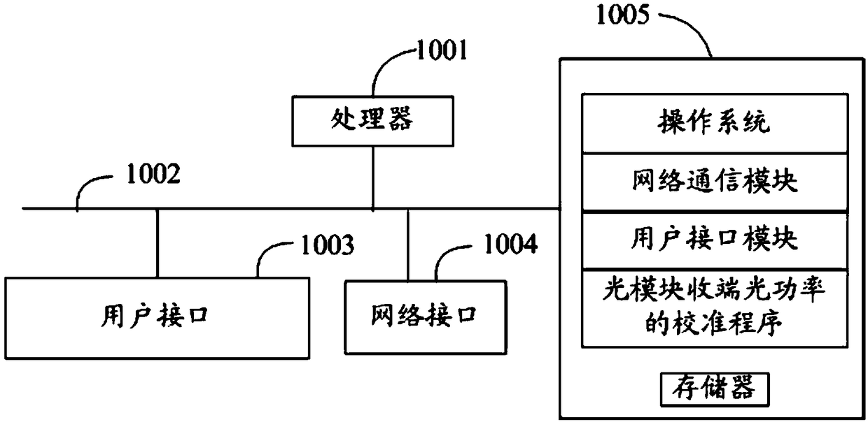
technical field [0001] The present invention relates to the technical field of optical module optical receivers, in particular to a method, device and readable storage medium for calibrating optical power at the receiving end of an optical module. Background technique [0002] The traditional optical module optical receiver monitors the input optical power of the avalanche photodiode APD inside the optical module: when the input optical power inputPower is a certain light (hereinafter referred to as Pi), the monitoring current I is mirrored by the current flowing through the APD. and the sampling resistor R to obtain a sampling voltage V (V=I*R), and use an ADC digital-to-analog converter to digitize the value of the voltage V and record it as an ADC. At this time, the optical power value reported by the receiving end of the optical module is Ptarget (hereinafter referred to as Pt). However, because the avalanche photodiode APD is often subjected to the avalanche voltage V ...

Claims


Application Information

Patent Timeline
IPC IPC(8): H04B10/079
CPCH04B10/07955
Inventor 熊伟霖姚海军庄礼杰
Owner APAT OPTOELECTRONICS COMPONENTS
Why Eureka
Eureka Blog
Learn More