Method for assembling middle frame and display component of electronic device, electronic device

A technology for display components and electronic equipment, applied in mechanical equipment, connecting components, measuring devices, etc., can solve problems such as heavy workload, insufficient assembly accuracy, hidden dangers of products, etc., achieve high shape accuracy, improve assembly accuracy, and reduce workload effect

Active Publication Date: 2021-04-09
OPPO CHONGQING INTELLIGENT TECH CO LTD
View PDF8 Cites 0 Cited by
  • Summary
  • Abstract
  • Description
  • Claims
  • Application Information

AI Technical Summary

Problems solved by technology

[0003] Among them, since the process of glue path detection is after glue spraying, refer to figure 1 , the adhesive surface 120 of the middle frame 100 has been covered by the adhesive layer 122 during detection, so it is impossible to judge whether the adhesive layer 122 is qualified based on it, and only by establishing a basic model as a reference
However, there are size differences between different middle frame molds provided by different suppliers, so it is necessary to model each set of middle frame molds separately, and the workload is very large
Moreover, if any set of middle frame molds is not modeled, it may lead to defects, which in turn may cause hidden dangers in the product
[0004] In addition, during the process of CCD alignment and screen installation, the adhesive surface 120 is also covered by the adhesive layer 122 during alignment, so the side 121 of the adhesive surface or the side 111 of the top surface cannot be used as the alignment reference, but only Using the largest outer edge 112 of the middle frame 100 as the alignment reference, when the middle frame 100 is assembled with the display assembly 200, because the side 111 of the top surface of the middle frame and the outer surface 211 of the display assembly are not used as the alignment reference, but There is no direct size correlation, which easily leads to insufficient assembly accuracy

Method used


Image

  • Method for assembling middle frame and display component of electronic device, electronic device
  • Method for assembling middle frame and display component of electronic device, electronic device
  • Method for assembling middle frame and display component of electronic device, electronic device

Examples


Embodiment Construction

[0041] The following describes the embodiments of the present invention in detail, and those skilled in the art will understand that the following embodiments are intended to explain the present invention, and should not be regarded as limiting the present invention. Unless otherwise specified, in the following examples that do not explicitly describe specific techniques or conditions, those skilled in the art can carry out according to commonly used techniques or conditions in this field or according to product instructions.

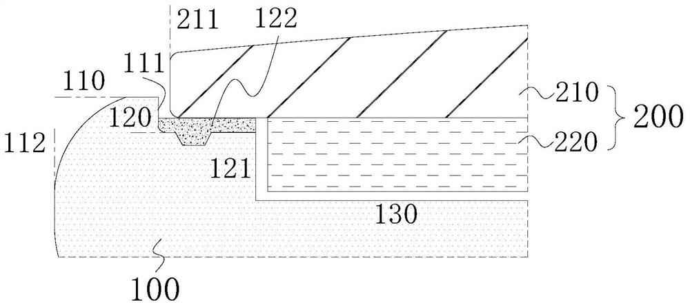
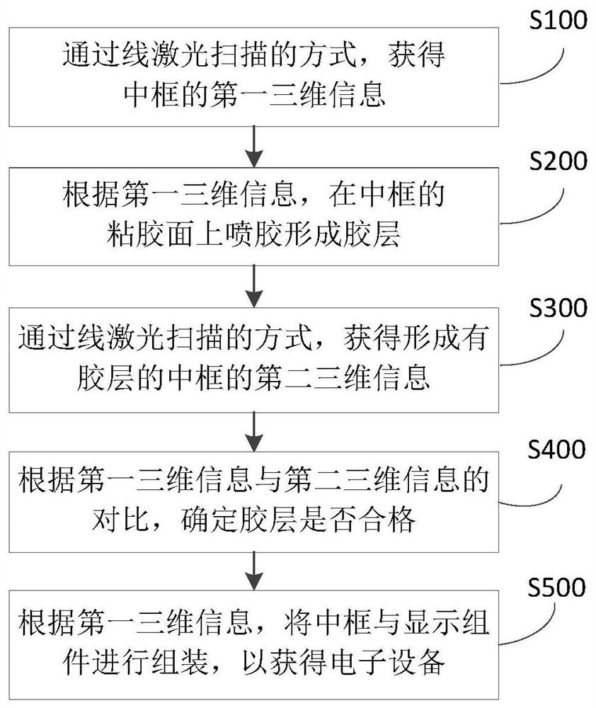
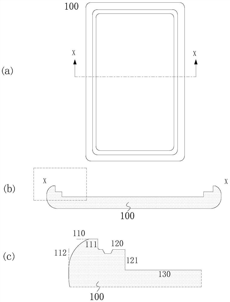
[0042] In one aspect of the embodiments of the present invention, a method for assembling a middle frame and a display component of an electronic device is provided. According to an embodiment of the present invention, refer to figure 2 , the assembly method includes:

[0043] S100: Obtain the first three-dimensional information of the middle frame by means of line laser scanning.

[0044] In this step, the original first three-dimensional informatio...


PUM


Abstract

The invention provides a method for assembling a middle frame of an electronic device and a display component, and the electronic device. The method for assembling the middle frame and the display component of the electronic device includes: obtaining the first three-dimensional information of the middle frame by means of line laser scanning; according to the first three-dimensional information, spraying glue on the adhesive surface of the middle frame to form a glue layer; By means of line laser scanning, the second three-dimensional information of the middle frame formed with the glue layer is obtained; according to the comparison between the first three-dimensional information and the second three-dimensional information, it is determined whether the glue layer is qualified; according to the first three-dimensional information, the middle frame and the second three-dimensional information are compared. Display components are assembled to obtain electronic devices. In the assembly method proposed by the present invention, the detection step is to compare the three-dimensional contours before and after spraying glue, which can more accurately determine whether the glue layer is qualified, and reduce the workload of establishing the basic model of the mold. The sides of the top surface of the middle frame obtained by scanning are aligned and assembled, which can further improve the assembly accuracy of the middle frame and the display component.

Description

technical field [0001] The invention relates to the technical field of glue coating detection and packaging, in particular, the invention relates to a method for assembling a middle frame of an electronic device and a display component, and the electronic device. Background technique [0002] At this stage, the mainstream process trend of narrow frame dispensing of mobile phones, tablet computers, smart watches and other electronic devices is to spray glue on the narrow frame first, then conduct glue path detection, and finally charge-coupled device (CCD) alignment screen, Moreover, the three-step process is completed separately by glue spraying machine, glue path testing equipment and CCD screen loading equipment, so there is no connection between the three equipment schemes. [0003] Among them, since the process of glue path detection is after glue spraying, refer to figure 1 , the adhesive surface 120 of the middle frame 100 has been covered by the adhesive layer 122 du...

Claims


Application Information

Patent Timeline
Patent Type & Authority Patents(China)
IPC IPC(8): G01B11/24F16B11/00
CPCF16B11/006G01B11/24
Inventor 董康
Owner OPPO CHONGQING INTELLIGENT TECH CO LTD
Why Eureka
Try Eureka