Vision-based trackless electric door running control method, device and system

A trackless electric door, operation control technology, applied in door/window accessories, power control mechanism, wing leaf control mechanism, etc., can solve the problems of destroying the beauty of the ground and the physical structure, low installation efficiency, high installation cost, etc., to achieve artificial Installation cost reduction, installation cost reduction, installation efficiency improvement effect

Active Publication Date: 2019-02-01
HUIZHOU TOPBAND ELECTRICAL TECH CO LTD
View PDF10 Cites 4 Cited by
  • Summary
  • Abstract
  • Description
  • Claims
  • Application Information

AI Technical Summary

Problems solved by technology

[0003] However, there are certain defects in these two methods. For the guide rail method, because the guide rail protrudes from the ground, the vehicle will bump and shake when the vehicle passes by, and the guide rail will be damaged due to the frequent rolling of the vehicle. In addition, the guide rail protrudes from the ground. Affect the appearance
For the magnetic nail method, it is necessary to drill holes in the ground during installation, which not only destroys the beauty and physical structure of the ground itself, but also increases the installation labor cost and material cost. The installation cost is high and the installation efficiency is low.

Method used


Image

  • Vision-based trackless electric door running control method, device and system
  • Vision-based trackless electric door running control method, device and system
  • Vision-based trackless electric door running control method, device and system

Examples


Embodiment 2

[0080] The second embodiment further includes the following steps on the basis of the first embodiment:

[0081] Specifically, step S4 includes:

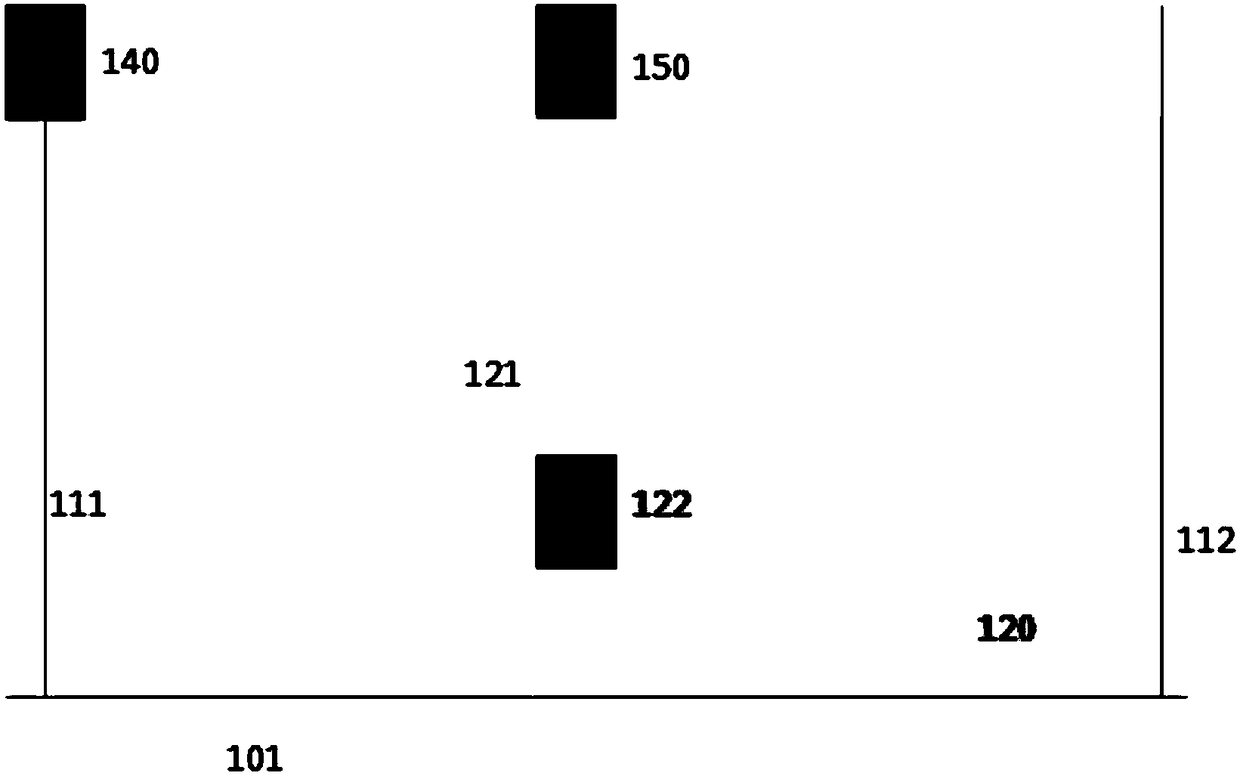
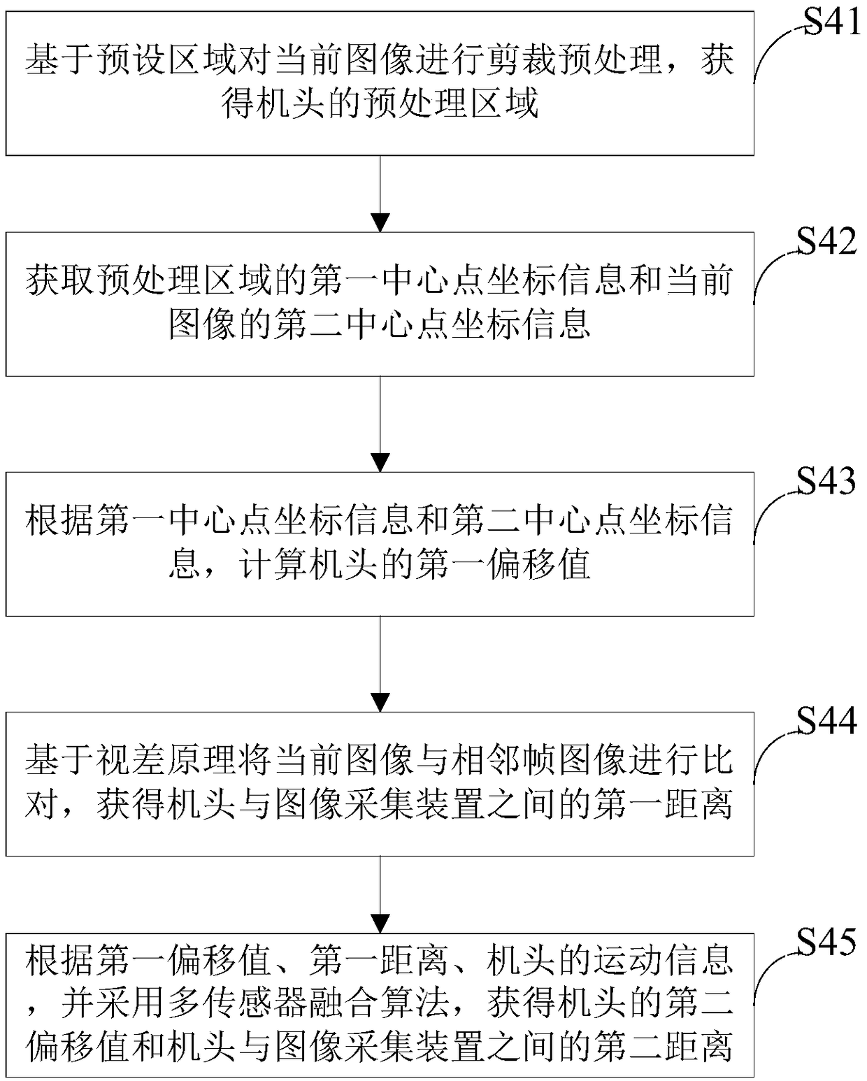
[0082] Step S41: Perform crop preprocessing on the current image based on the preset area to obtain the preprocessing area of ​​the handpiece 121.

[0083] Step S42: Obtain the first center point coordinate information of the preprocessing area and the second center point coordinate information of the current image.

[0084] S43: According to the first center point coordinate information and the second center point coordinate information, a first offset value of the computer head 121.

[0085] Take d 1 Represents the first offset value, then the first offset value d 1 It can be obtained in the following ways:

[0086] Specifically, suppose that the abscissa in the first center point coordinate information of the preprocessing area is x1, and the abscissa in the second center point coordinate information of the current image is x2. Then, under...


PUM


Abstract

The invention relates to a vision-based trackless electric door running control method, device and system. The method comprises the steps of S1, acquiring a current image, collected by an image acquisition device, of an electric door in the moving direction; S2, extracting current features of the current image through a preset method, comparing the extracted current features of the current image with prestored features to judge whether the current features are matched with the prestored features or not, if yes, executing the step S4, and if not, executing the step S3; S3, outputting a controlsinal to control the electric door to stop; S4, conducting analytical processing on the current image and acquiring skewing information of a machine head of the electric door through combination withmotion information of the machine head of the electric door; and S5, controlling the electric door to operate according to the skewing information to the machine head. Through the method, traditionalmagnetic nails or guide rails can be effectively omitted; an obstacle can be accurately avoided without an additional infrared sensor, navigation of the electric door can be more accurately realized,and the electric door is effectively prevented from skewing.

Description

Technical field [0001] The invention relates to the field of door control, and more specifically, to a vision-based method, device and system for controlling the operation of a trackless electric door. Background technique [0002] The gates of factories, schools and other places are generally opened or closed by one or more motors driving fence-like gates. At present, most electric doors on the market are embedded with guide rails or magnetic nails on the ground, and the movement direction of the electric door is controlled by the guide rails or magnetic nails to prevent the electric door from deviating. [0003] However, these two methods have certain defects. For the guide rail method, because the guide rail protrudes from the ground, the vehicle will bump and shake when the vehicle passes, and the guide rail will be damaged due to frequent rolling of the vehicle. In addition, the guide rail protrudes from the ground. Affect the appearance. For the magnetic nail method, it is ...

Claims


Application Information

Patent Timeline
Patent Type & Authority Applications(China)
IPC IPC(8): E05F15/73E05F15/70
CPCE05Y2900/132E05F15/70E05F15/73E05F2015/767
Inventor 徐一新
Owner HUIZHOU TOPBAND ELECTRICAL TECH CO LTD
Why Eureka
Try Eureka