
Inner side fixed type optical fiber transfer device and operation method thereof

A transfer device, fixed technology, applied in the direction of transportation and packaging, conveyors, conveyor objects, etc., can solve the problems of low transfer efficiency, inaccurate transfer, difficult to observe with the naked eye, etc., and achieve the effect of high transfer efficiency

Active Publication Date: 2019-02-01
ZHEJIANG HOUDAR INTELIGENT TECH CO LTD
View PDF4 Cites 0 Cited by
  • Summary
  • Abstract
  • Description
  • Claims
  • Application Information

AI Technical Summary

Problems solved by technology

[0007] The purpose of the present invention is to provide an inner fixed optical fiber transfer device, which solves the defect that the existing optical fiber transfer device can only remove a single optical fiber reel at a time, and its removal efficiency is low
[0008] Another object of the present invention is to provide an operation method for an optical fiber transfer device, which solves the defects that the optical fiber reel is dimly lit in the hydrogen loss test kettle, difficult to observe with naked eyes, and inaccurate in transfer.

Method used


Image

  • Inner side fixed type optical fiber transfer device and operation method thereof
  • Inner side fixed type optical fiber transfer device and operation method thereof
  • Inner side fixed type optical fiber transfer device and operation method thereof

Examples


Embodiment 1

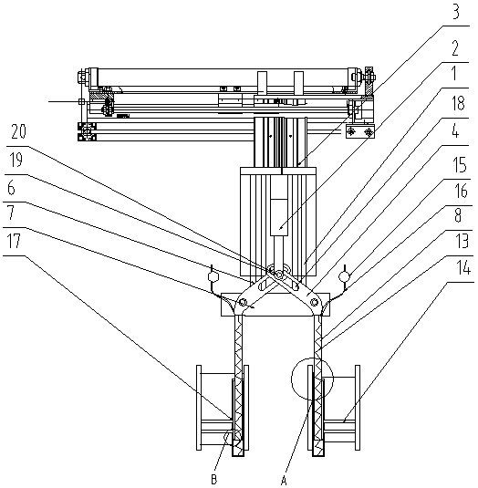
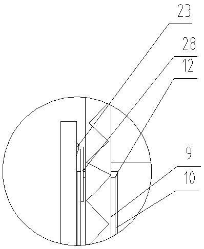
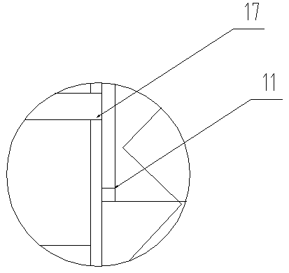
[0035] Such as figure 1 , figure 2 , image 3 , Figure 4 , Figure 5 , Figure 6 and Figure 7 As shown, a kind of inner fixed optical fiber transfer device provided by the present invention includes: lift cylinder 1, telescopic cylinder 2, lift 3 and a pair of oblique arms 4, the top of the lift cylinder is fixed on the lift; the lift cylinder has Lifting rod 6, the end of the lifting rod is equipped with a fixed plate 7, one end of a pair of said oblique arms is respectively hinged on the two ends of the fixed plate, the other end of said oblique arm is equipped with an internal hollow telescopic rod 8, said telescopic rod It includes a hollow inner rod 9 and a hollow outer rod 10 sheathed on the inner rod, the outer rod can slide along the outer wall of the inner rod, the outer end wall of the inner rod has a stopper 11, the inner side of the outer rod A stop ring 12 is provided on the end wall; a spring 13 is provided inside the outer rod, one end of the spring is ...

Embodiment 2

[0040] The invention also discloses an operation method of an optical fiber transfer device, which includes the following steps:

[0041] 1) When the optical fiber transfer device is in the middle of two groups of optical fiber reels, the control unit sends a signal to the elevator, lifting cylinder and telescopic cylinder, so that the elevator and lifting cylinder push the fixed plate down, and the extension arm of the telescopic cylinder is downward Stretch; at this time, the control unit opens the gas flow control valve so that the output pressure P of the gas flow control valve 1 1 ;

[0042] 2) When the sounding shell on the upper part of the telescopic rod is close to the inner wall of the fiber optic reel, the gas in the sounding shell touches the fiber optic reel to make a sound, and the sound sensor collects the sound signal from the sounding shell and sends the sound signal to the control unit; control The unit controls the elevator and the lifting cylinder to stop ...


PUM


Abstract

The invention discloses an inner side fixed type optical fiber transfer device. The inner side fixed type optical fiber transfer device comprises a lifting air cylinder, a telescopic air cylinder, anlifter and a pair of inclined arms, wherein the top end of the lifting air cylinder is fixed on the lifter, the lifting air cylinder is provided with a lifting rod, the tail end of the lifting rod isprovided with a fixing plate, and one ends of the pair of inclined arms are hinged to the two ends of the fixing plate correspondingly; the other ends of the inclined arms are provided with internallyhollow telescopic rods, two pairs of telescopic cylinders which are opposite to each other and transversely extend out are installed at the bottom ends of the telescopic rods, the inner cavities of the telescopic rods communicate with external high-pressure gas through air pipes, and gas flow control valves are installed on the air pipes; the inner cavities of the telescopic cylinders communicatewith the telescopic rods through vent holes, strip-shaped sliding holes are formed in the inclined arms, the sliding holes of the pair of inclined arms are overlapped to form an overlapping area, oneend of a stretching arm of the telescopic air cylinder is provided with a bolt, and the bolt is inserted into the overlapping area; and the other ends of the telescopic cylinders are fixed on the lifter. According to the device and the method, two optical fiber winding rolls can be moved at one step through the cooperation of the telescopic air cylinder, the telescopic rods and the telescopic cylinders, and removal efficiency of the device is high.

Description

technical field [0001] The invention relates to the field of optical fiber manufacturing, in particular to an inner fixed optical fiber transfer device and an operating method thereof. Background technique [0002] The tiny fiber is encapsulated in a plastic sheath that allows it to be bent without breaking. Typically, a transmitter at one end of the fiber uses a light-emitting diode or a laser to send pulses of light into the fiber, and a receiver at the other end of the fiber uses a photosensitive element to detect the pulses. [0003] In daily life, optical fibers are used for long-distance information transmission because the loss of light in optical fibers is much lower than that of electricity in wires. [0004] Usually the terms optical fiber and optical cable are confused. Most optical fibers must be covered by several layers of protective structures before use, and the coated cables are called optical cables. The protective layer and insulating layer on the outer...

Claims


Application Information

Patent Timeline
Patent Type & Authority Applications(China)
IPC IPC(8): B65G47/91
CPCB65G47/912B65G47/917B65G2201/0217
Inventor 蔡永潮
Owner ZHEJIANG HOUDAR INTELIGENT TECH CO LTD
Learn More