
Position detection system and position detection method for tire building drum

A tire building drum and detection method technology, which is applied in the field of tire building, can solve the problems of unqualified turned-up products, inability to switch freely, and inability to judge whether the turned-up action is normal, etc., and achieve the effect of accurate detection results and convenient adjustment

Active Publication Date: 2019-02-01
SAFE RUN & HISCENT MACHINERY SUZHOU
View PDF8 Cites 3 Cited by
  • Summary
  • Abstract
  • Description
  • Claims
  • Application Information

AI Technical Summary

Problems solved by technology

[0003] During the turn-up process, if some turn-up rods cannot be turned up in place, the composite layer and ply on the axially outer side of the bead cannot be fully attached to the carcass assembly formed by inflation.
After the turn-up is completed, some turn-up rods cannot return to the initial position, which will cause the outer surface of the tire building drum to bulge, and when the tire building drum continues to rotate the material, it will cause the turn-up rods to swing or the rubber to bulge and break
Existing tire building drums often use pressure switches to detect the pressure value to determine whether the turn-up lever is back in place, but it cannot detect whether the turn-up lever is raised to the position, so it cannot be judged whether the turn-up action is normal, which may easily cause turn-up product failures
In addition, for tires of different specifications, when the tire parameters change, they cannot be switched freely, and the scope of use is limited

Method used


Image

  • Position detection system and position detection method for tire building drum
  • Position detection system and position detection method for tire building drum
  • Position detection system and position detection method for tire building drum

Examples


Embodiment Construction

[0041] In order to make the technical problems solved by the present invention, the technical solutions adopted and the technical effects achieved clearer, the technical solutions of the present invention will be further described below in conjunction with the accompanying drawings and through specific implementation methods. It should be understood that the specific embodiments described here are only used to explain the present invention, but not to limit the present invention. In addition, it should be noted that, for the convenience of description, only the parts related to the present invention are shown in the drawings but not all of them.

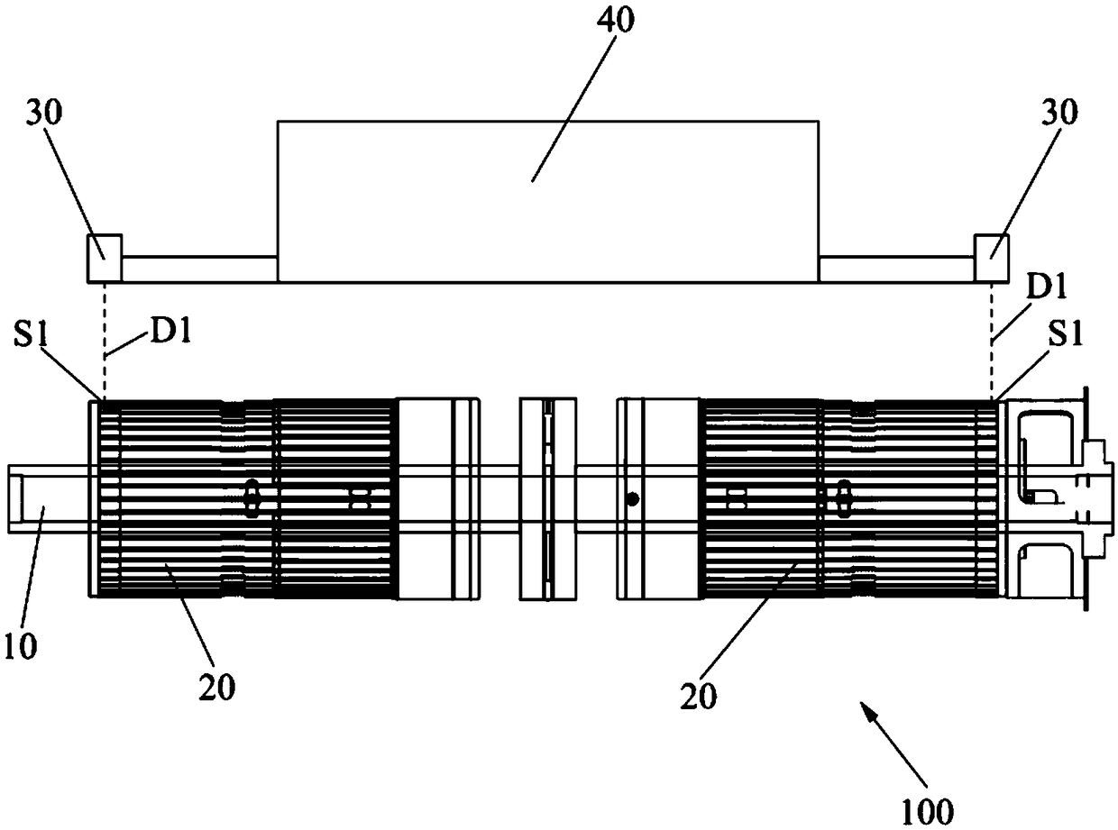
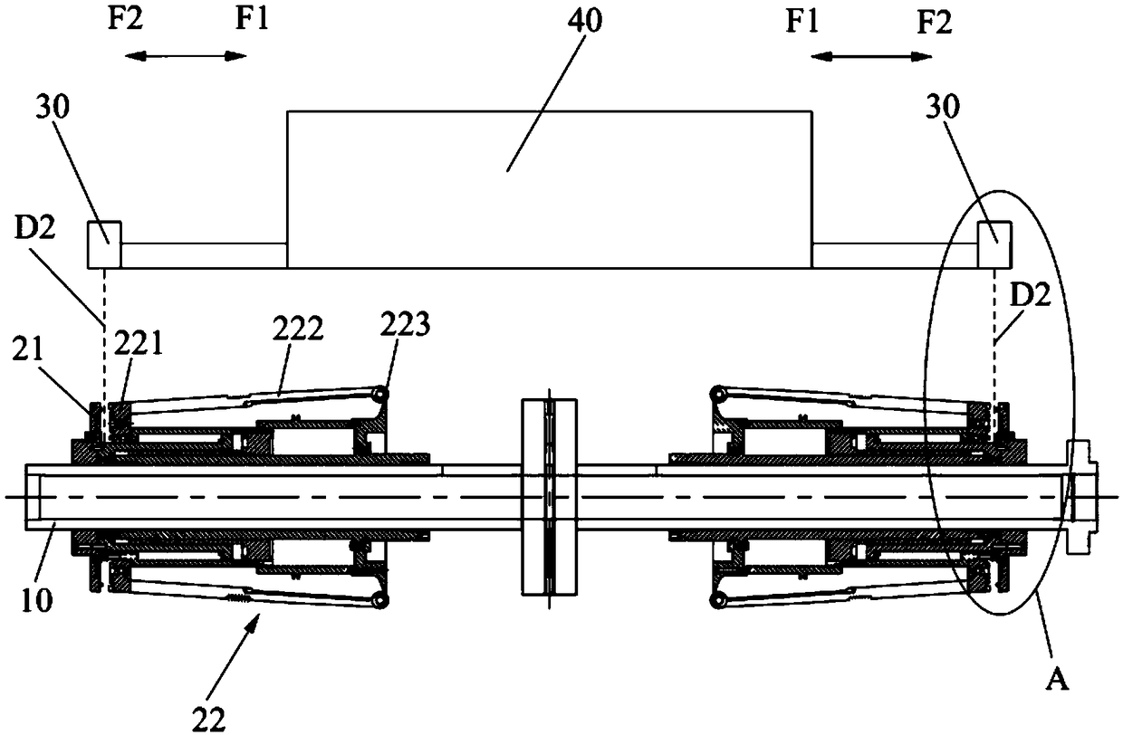
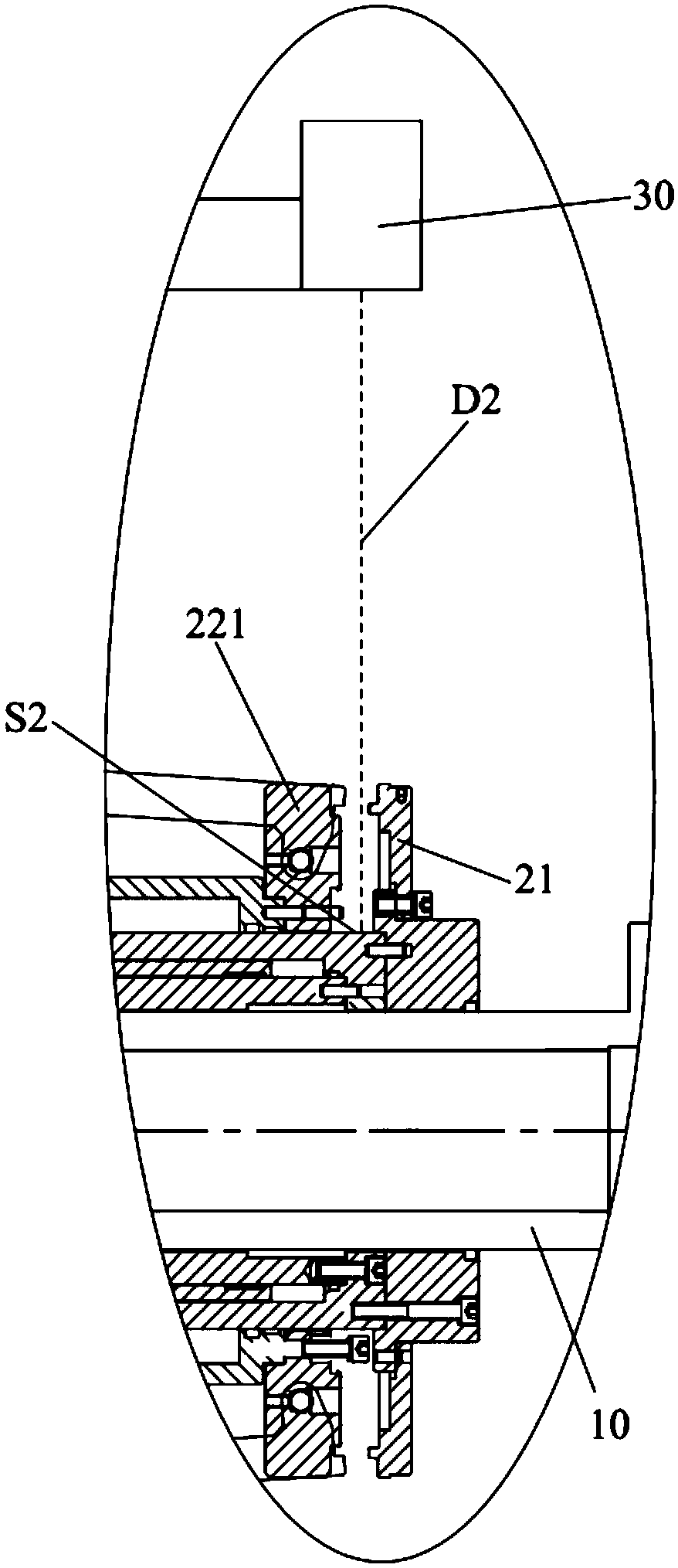
[0042] see Figure 1 to Figure 4 , the embodiment of the present invention provides a position detection system installed on a tire building machine (not shown), the position detection system is used to detect the position of the movable parts on the tire building drum 100, to confirm whether the movable parts Move in place. If the...


PUM


Abstract

The invention discloses a position detection system and a position detection method for a tire building drum, and belongs to the technical field of tire building. The position detection system comprises two ranging components, a drive unit and a control unit, wherein the two ranging components are arranged at the radial outer side of the tire building drum, and radially aligned with support discson two anti-package rod assemblies separately; the drive unit is used for driving the synchronous opposite or reverse axial movement of the two ranging components; and the control unit is in signal connection with the drive unit and the tire building drum, and used for controlling the movement of the anti-package rod assemblies and controlling the working state of the drive unit. The position detection method is based on the position detection system, and used for carrying out position confirmation on the anti-package rod assemblies on the tire building drum. The drive unit is capable of driving the ranging components to detect at different positions, so that a more accurate detection result is achieved; and moreover, the movement distances of the two ranging components can be adjusted, then different tires are matched, and convenient adjustment is achieved.

Description

technical field [0001] The invention relates to the technical field of tire building, in particular to a position detection system and a position detection method for a tire building drum. Background technique [0002] At present, the tire building drum of the tire building machine includes a drum shaft and two half-drums axially spaced on the drum shaft. The half-drum includes a turn-up rod assembly, which includes several turn-up rods arranged around the drum axis. When the composite plies and plies of a tire are supplied to a carcass assembly forming a circumference on a tire building drum, two opposing beads are mounted axially spaced apart from the carcass assembly to form a Seal the space, while inflating the space between the two opposite beads, drive several turn-up rods on both sides to move relative to each other from the initial position, so as to turn up the composite layer and the ply on the axially outer side of the bead On the carcass assembly formed by infl...

Claims


Application Information

Patent Timeline
Patent Type & Authority Applications(China)
IPC IPC(8): B29D30/24B29D30/26
CPCB29D30/24B29D30/26
Inventor 李志军
Owner SAFE RUN & HISCENT MACHINERY SUZHOU
Learn More