
A reaction kettle with high temperature and high pressure resistance and stirring function for chemical machinery

A technology of chemical machinery and high temperature resistance, which is applied in the field of high temperature and high pressure resistant reaction kettles for chemical machinery with stirring function, can solve the problems of inconvenient placement of the main body, inability to achieve mixing, and unsatisfactory effects, achieve good protection effect, and increase stirring performance. , the effect of good elasticity

Active Publication Date: 2020-11-10
HUANGSHAN BONSUN PHARMA
View PDF6 Cites 0 Cited by
  • Summary
  • Abstract
  • Description
  • Claims
  • Application Information

AI Technical Summary

Problems solved by technology

[0004] The object of the present invention is to provide a reaction kettle with high temperature and high pressure resistance and stirring function for chemical machinery, to solve the problem that the existing reaction kettle proposed in the background technology is too simplified due to the internal structure, which leads to many defects in the body during use. Disadvantages, such as the inability to fully stir the internal materials, which will lead to unsatisfactory material processing effects and the inability to achieve the purpose of sufficient mixing. At the same time, the main body is not convenient for stable placement, resulting in easy damage to the main body. question

Method used


Image

  • A reaction kettle with high temperature and high pressure resistance and stirring function for chemical machinery
  • A reaction kettle with high temperature and high pressure resistance and stirring function for chemical machinery
  • A reaction kettle with high temperature and high pressure resistance and stirring function for chemical machinery

Examples


Embodiment Construction

[0026] The following will clearly and completely describe the technical solutions in the embodiments of the present invention with reference to the accompanying drawings in the embodiments of the present invention. Obviously, the described embodiments are only some, not all, embodiments of the present invention. Based on the embodiments of the present invention, all other embodiments obtained by persons of ordinary skill in the art without making creative efforts belong to the protection scope of the present invention.

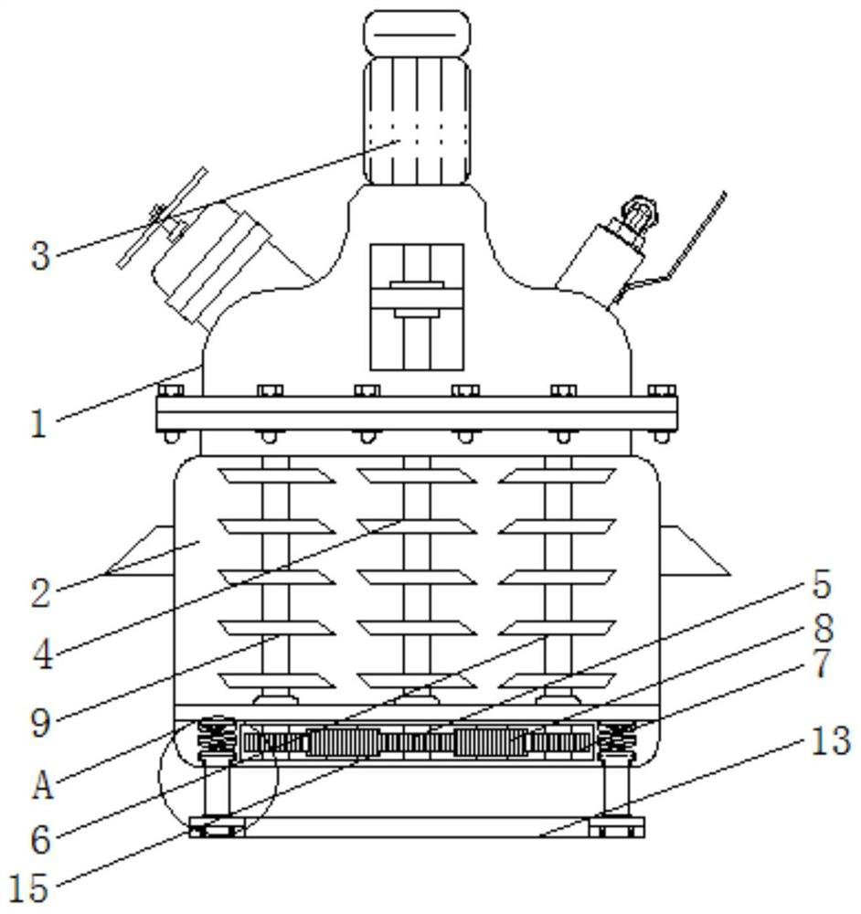
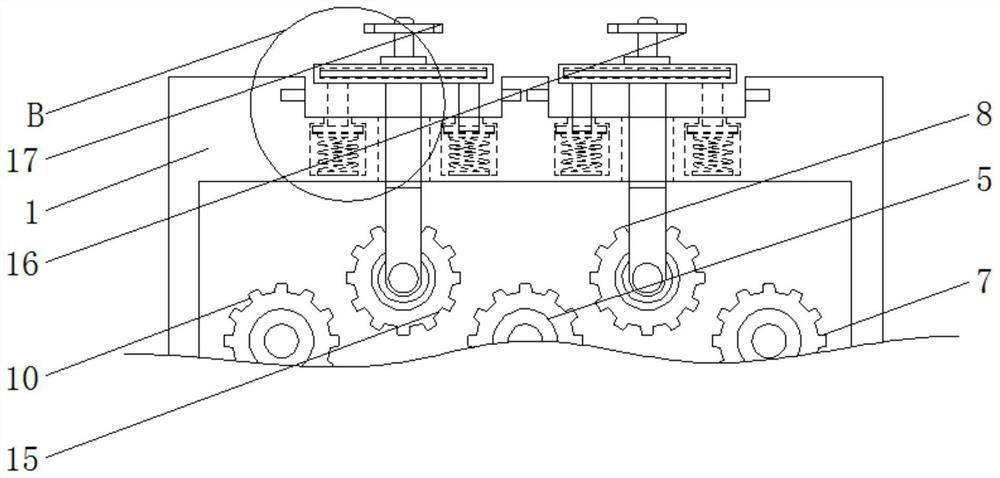
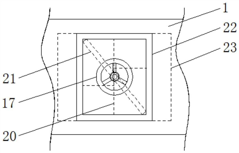
[0027] see Figure 1-5, the present invention provides a technical solution: a reaction kettle with high temperature and high pressure resistance and stirring function for chemical machinery, including a kettle body 1, an inner chamber 2, a motor 3, a central stirring shaft 4, a central gear 5, and a first auxiliary stirring shaft 6. The first sub-gear 7, the first interlocking gear 8, the second sub-stirring shaft 9, the second sub-gear 10, the damping spring...


PUM


Abstract

The invention relates to a high-temperature and high-pressure resistant reaction kettle for chemical machinery and with a stirring function. The reaction kettle comprises a kettle body and a first auxiliary stirring shaft. An inner chamber is arranged at the middle part of the kettle body, and the top of the kettle body is provided with a motor. A central stirring shaft is installed at the centerof the inner chamber, and the lower end of the central stirring shaft is connected with a sun gear. A first auxiliary gear is connected to the lower end of the first auxiliary stirring shaft, and thefirst auxiliary stirring shaft is positioned at the right end of the central stirring shaft. A first linked gear is connected to the outer end of the first auxiliary gear. A second auxiliary stirringshaft is installed at the left end of the central stirring shaft. the invention has the following beneficial effects: as the high-temperature and high-pressure resistant reaction kettle for chemical machinery and with a stirring function is equipped with a telescopic spring, a limited post can be jacked up inside a connection tank through the elastic force of the telescopic spring so as to drive asecond connection mechanism to move outwards and endow the second connection mechanism with good reset performance and greatly restrict an idle second linked gear.

Description

technical field [0001] The invention relates to the technical field of reactor devices, in particular to a reactor for chemical machinery that is resistant to high temperature and high pressure and has a stirring function. Background technique [0002] The broad understanding of the reactor is a container with physical or chemical reactions. Through the structural design and parameter configuration of the container, the heating, evaporation, cooling and low-speed mixing functions required by the process are realized. The reactor is widely used in petroleum, chemical, Rubber, pesticides, dyes, medicines, food, pressure vessels used to complete vulcanization, nitration, hydrogenation, alkylation, polymerization, condensation and other processes, such as reactors, reaction pots, decomposition pots, polymerization kettles, etc.; materials generally have carbon Manganese steel, stainless steel, zirconium, nickel-based alloys and other composite materials. [0003] Due to the ove...

Claims


Application Information

Patent Timeline
Patent Type & Authority Patents(China)
IPC IPC(8): B01J19/18
CPCB01J19/0053B01J19/0066B01J19/18
Inventor 查春妹程跃光
Owner HUANGSHAN BONSUN PHARMA
Learn More