A system for writing in patients with Parkinson's disease
A technology for syndromes and patients, applied in the field of writing systems for patients with Parkinson's syndrome, can solve the problems of ignoring the effects of myotonia and Parkinson's disease supplies, and achieve a stable effect
- Summary
- Abstract
- Description
- Claims
- Application Information
AI Technical Summary
Problems solved by technology
Method used
Image

Examples
Embodiment 1
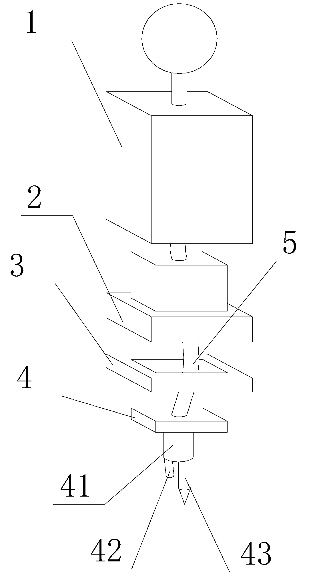
[0040] Such as Figure 7 As shown, a system for patients with Parkinson's syndrome to write in the present invention includes a control part 2; the control part 2 includes a control cavity 22, and a control device 23 is arranged in the control cavity 22; the control The device 23 includes: a power supply module for power supply; an image recognition module for recognizing images collected by the camera 42; a drive module for supplying power to the coil A37 and coil B; a buzzer for sounding an alarm; A gyroscope for collecting the acceleration of the control device 23; a control module for controlling the work of the driving module according to the image information collected by the image recognition module and the acceleration information collected by the gyroscope.
[0041] During the implementation of this embodiment, the inventor carefully studied the resting tremor and muscle rigidity of Parkinson's patients and found the following characteristics. For Parkinson's patient'...
Embodiment 2
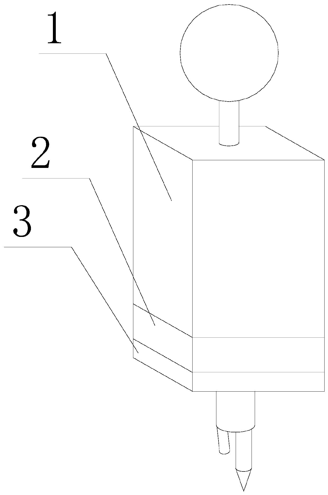
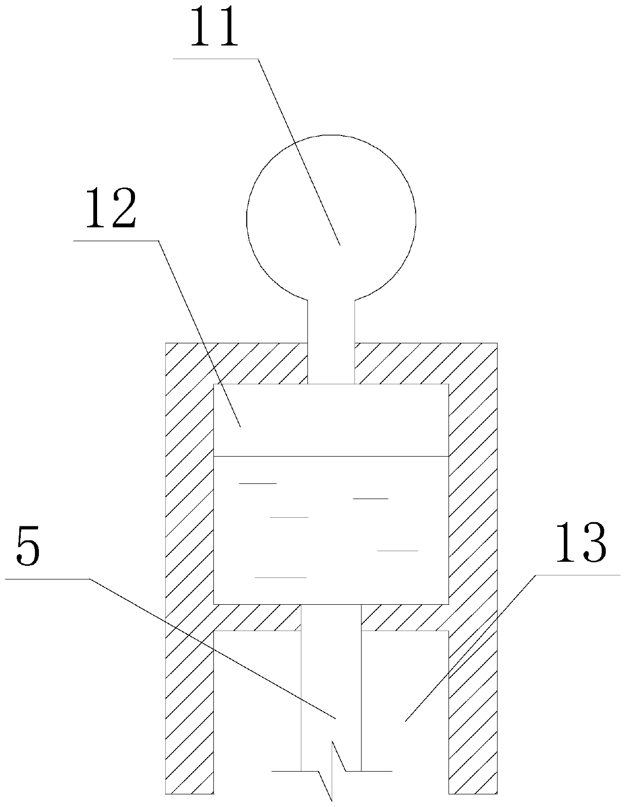
[0043] Such as Figure 1~6 As shown, on the basis of Embodiment 1, this embodiment also includes an ink storage part 1, an execution part 3 and a terminal part 4; the ink storage part 1, the control part 2, the execution part 3 and the end part 4 are connected in sequence; it also includes an ink delivery hose 5; an ink storage room 12 is set in the ink storage part 1, and ink is stored in the ink storage room 12; a through hole is set on the outer wall of the control cavity 22 facing the execution part 3 24, and the control device 23 is connected to the execution part 3 by a wire and controls the movement of the execution part 3, and the wire passes through the through hole 24; Support 33; the outer frame 31 is a square ring, and a square ring chute 35 is set on the inner ring side wall of the square ring; the square ring chute 35 includes a pair of parallel X-direction chute and a pair of The Y-direction chute arranged in parallel; the X-direction chute is orthogonal to the...
Embodiment 3
[0048] In this embodiment, on the basis of Embodiment 2, the executive part 3 further includes a pin 34; the pin 34 is movably linked to the X-direction movement cross brace 32 and the Y-direction movement cross brace 33; when the X-direction movement cross brace 32 and When the Y-direction moving cross brace 33 moves relative to each other, the pin 34 moves along the axis of the X-direction moving cross brace 32 or / and along the axis of the Y-direction moving cross brace 33 ; the pin 34 is fixedly connected to the end member 4 .
[0049] During the implementation of this embodiment, in order to realize the operation of the actuator part 3 driving the terminal part 4, the above-mentioned settings are made, which allows the pin 34 to effectively move to any position in the box 31, and the pin 34 drives the terminal part. 4 pieces of movement.
PUM
 Abstract
Description
Claims
Application Information
 - R&D
- Intellectual Property
- Life Sciences
- Materials
- Tech Scout
- Unparalleled Data Quality
- Higher Quality Content
- 60% Fewer Hallucinations
Browse by: Latest US Patents, China's latest patents, Technical Efficacy Thesaurus, Application Domain, Technology Topic, Popular Technical Reports.
© 2025 PatSnap. All rights reserved.Legal|Privacy policy|Modern Slavery Act Transparency Statement|Sitemap|About US| Contact US: help@patsnap.com