
A wiring detection method and detection system

A detection method and square wave signal technology, which are applied in electrical connection testing, measuring devices, engine testing, etc., can solve problems such as difficulty in troubleshooting, difficulty in starting, and confusion between positive and negative, and achieve the effect of reducing the difficulty of troubleshooting.

Active Publication Date: 2020-11-20
WEICHAI POWER CO LTD
View PDF8 Cites 0 Cited by
  • Summary
  • Abstract
  • Description
  • Claims
  • Application Information

AI Technical Summary

Problems solved by technology

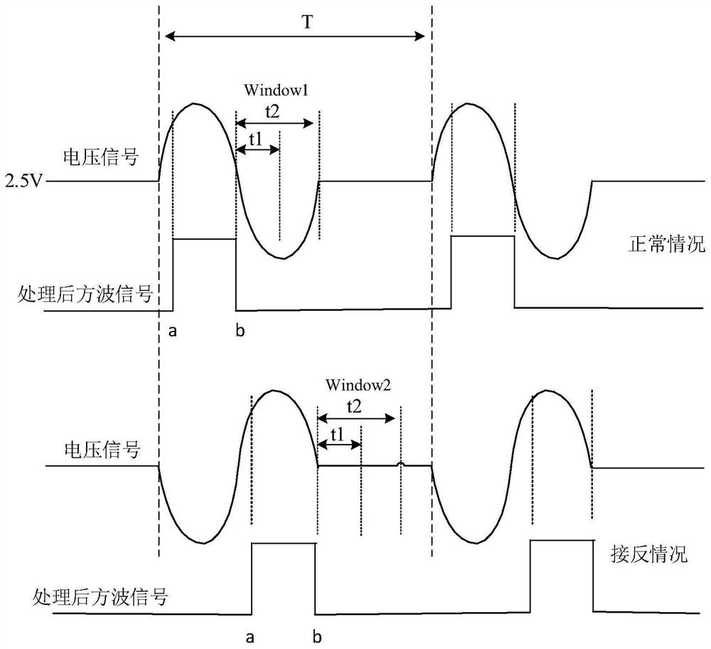
[0003] The camshaft signal disc of the engine has two types: perforated and protruding teeth. The positive and negative wiring modes corresponding to these two signal discs are opposite. It is easy to confuse the positive and negative poles when designing the wiring harness. When the positive and negative poles of the magnetoelectric sensor are connected to the If the timing is reversed, it may cause the engine to fail to start, difficult to start, without any fault performance (deviation of the actual advance angle), etc., and it is difficult to check

Method used


Image

  • A wiring detection method and detection system
  • A wiring detection method and detection system
  • A wiring detection method and detection system

Examples


Embodiment Construction

[0037] The present invention will be further described in detail below in conjunction with the accompanying drawings and embodiments. It should be understood that the specific embodiments described here are only used to explain the present invention, but not to limit the present invention. In addition, it should be noted that, for the convenience of description, only some structures related to the present invention are shown in the drawings but not all structures.

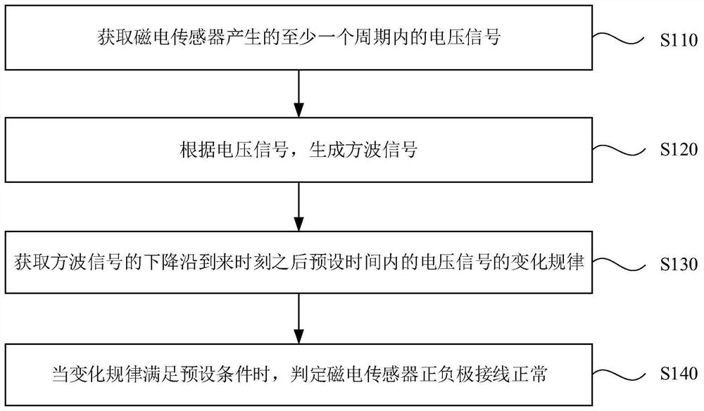
[0038] figure 1 It is a schematic flow chart of a wiring detection method provided by the embodiment of the present invention. This embodiment is applicable to the positive and negative wiring of the magnetoelectric sensor in the engine. The method includes:

[0039] Step 110, acquiring a voltage signal generated by the magnetoelectric sensor within at least one cycle.

[0040] Step 120, generating a square wave signal according to the voltage signal.

[0041] Step 130 , acquiring the change law of the voltage s...


PUM


Abstract

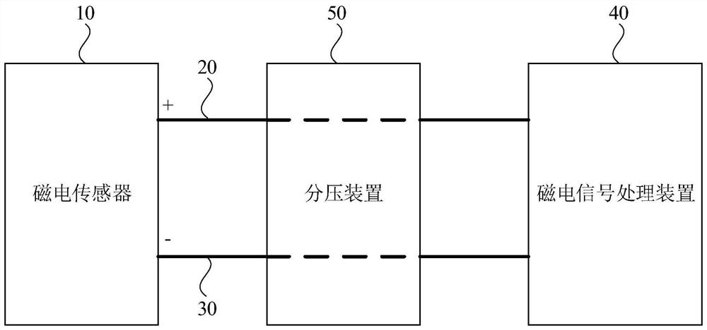
An embodiment of the invention discloses a wiring detection method and a wiring detection system. The wiring detection method comprises the steps of: acquiring voltage signals generated by an magnetoelectric sensor within at least one period; generating square wave signals according to the voltage signals; acquiring a variation law of the voltage signals within a preset time after a moment of arrival of falling edges of the square wave signals; and determining that positive and negative wiring of the magnetoelectric sensor is normal when the variation law satisfies a preset condition. The wiring detection method and the wiring detection system solve the problem of positive and negative wiring detection of the magnetoelectric sensor, can detect the fault of inverse connection of positive and negative electrodes, and reduce the difficulty of troubleshooting.

Description

technical field [0001] Embodiments of the present invention relate to engine control technology, and in particular to a wiring detection method and detection system. Background technique [0002] Magnetoelectric sensors are commonly used sensors in engines, and are generally used to detect the phase and rotational speed of crankshaft signal discs and camshaft signal discs. The principle is that when the magnetic flux outside the sensor changes, the voltage value of its output signal conforms to That is, voltage is proportional to the rate of change of magnetic flux. [0003] The camshaft signal disc of the engine has two types: perforated and protruding teeth. The positive and negative wiring modes corresponding to these two signal discs are opposite. It is easy to confuse the positive and negative poles when designing the wiring harness. When the positive and negative poles of the magnetoelectric sensor are connected to the If the timing is reversed, it may cause the eng...

Claims


Application Information

Patent Timeline
Patent Type & Authority Patents(China)
IPC IPC(8): G01M15/00G01R31/67
CPCG01M15/00G01R31/67
Inventor 王涛覃艳
Owner WEICHAI POWER CO LTD
Learn More