Building supporting frame structure

A support frame and building technology, applied in the field of support frames, can solve problems such as insufficient flexibility in structural design, insufficient firm structure of the device body, and potential safety hazards, so as to improve firmness and convenience, facilitate assembly and transfer, improve flexibility and The effect of convenience

Pending Publication Date: 2019-01-25
GUIZHOU NORMAL UNIVERSITY
View PDF7 Cites 0 Cited by
  • Summary
  • Abstract
  • Description
  • Claims
  • Application Information

AI Technical Summary

Problems solved by technology

[0004] The purpose of the present invention is to provide a kind of building support frame structure, to solve a kind of support frame disclosed in Chinese invention patent application publication specification CN104848015A proposed in the above-mentioned background technology, although this support frame is connected with the load-carrying arm through a rotating shaft , the supporting arm can rotate around the rotating shaft to a stable position, forming a supporting angle with the carrying arm, thereby supporting the carrying arm. The rotating shaft rotates to a stable position and forms a bearing angle with the support arm to carry portable electronic devices. However, the support frame can only be used to support electronic products, and there is a problem that it cannot support large heavy objects. For example, when a factory building is being built, More flexible, more stable and stronger support structures are needed, and the structural design of general support structures is not flexible enough, which leads to the problem of inconvenient assembly and disassembly of the structure. At the same time, the general device body also has insufficient structure. firm, which leads to the problem of potential safety hazards in the use of the device body

Method used


Image

  • Building supporting frame structure
  • Building supporting frame structure
  • Building supporting frame structure

Examples


Embodiment Construction

[0028] The following will clearly and completely describe the technical solutions in the embodiments of the present invention with reference to the accompanying drawings in the embodiments of the present invention. Obviously, the described embodiments are only some, not all, embodiments of the present invention.

[0029] In the description of the present invention, unless otherwise stated, the meaning of "plurality" is two or more; the terms "upper", "lower", "left", "right", "inner", "outer" , "front end", "rear end", "head", "tail", etc. indicate the orientation or positional relationship based on the orientation or positional relationship shown in the drawings, and are only for the convenience of describing the present invention and simplifying the description, rather than Nothing indicating or implying that a referenced device or element must have a particular orientation, be constructed, and operate in a particular orientation should therefore not be construed as limiting ...


PUM


Abstract

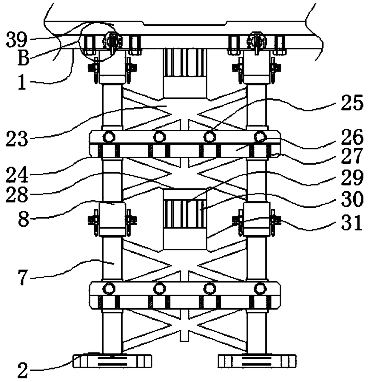
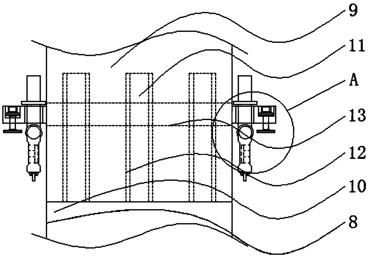
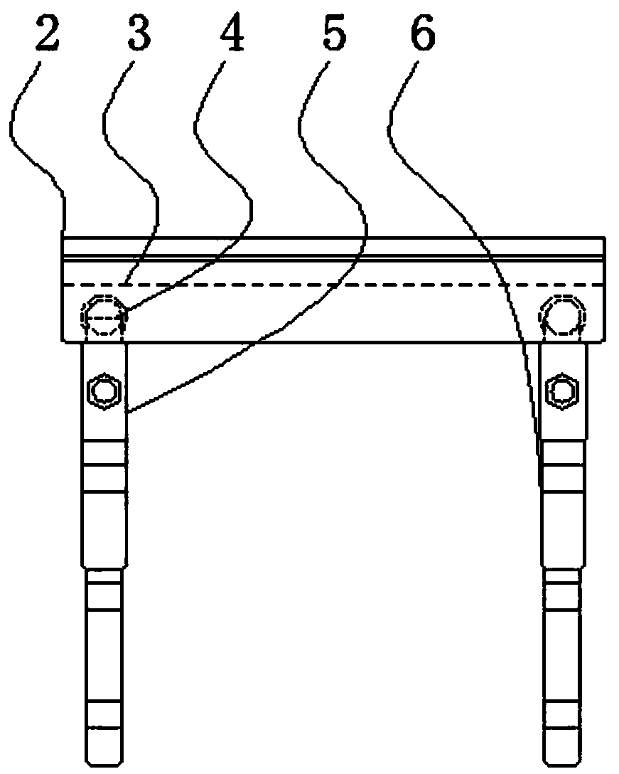
The invention relates to a building supporting frame structure. The building supporting frame structure comprises a frame body and a seat connecting penetrating rod, the bottom end of the frame body is connected with a fixing foot frame, the inner side of the fixing foot frame is provided with a connecting penetrating groove, the left end of the connecting penetrating groove is provided with a linkage rotating shaft, the outer end of the linkage rotating shaft is connected with a main steel fixing foot, the right side of the main steel fixing foot is provided with a main steel fixing foot, linkage surrounding columns are fixed on the middle section of the periphery of the frame body respectively, and the middles of the linkage surrounding columns are connected with linkage seats. The building supporting frame structure has the advantages that penetrating connecting notches and fixing blocks are arranged, fixed battens have the flexibility through the elasticity of connecting springs, so that the fixed battens tightly abut the fixing blocks at the outer sides of the penetrating connecting notches, thereby blocking the upper and lower ends of the penetrating connecting notches, facilitating the placement of cables penetrating through the penetrating connecting notches from the fixed battens, and facilitating wiring of the frame body.

Description

technical field [0001] The invention relates to the technical field of support frames, in particular to a building support frame structure. Background technique [0002] Support frame, as the name implies, the place where objects are fixed and bears weight and strength is called a support frame. In construction and production industries, support frames are often used to weigh and support workshops, while some workshops use concrete pouring to manufacture support columns. , and then to support the plant. [0003] A support frame disclosed in the Chinese invention patent application publication specification CN104848015A, although the support frame is rotatably connected to the carrying arm through a rotating shaft, the supporting arm can rotate around the rotating shaft to a stable position, forming a supporting angle with the carrying arm, thereby Supporting the carrying arm, the carrying part is accommodated in the front accommodating groove, and is rotatably connected to ...

Claims


Application Information

Patent Timeline
Patent Type & Authority Applications(China)
IPC IPC(8): E04G25/06
CPCE04G25/06
Inventor 陈燕菲倪焰陈敏孔鹏韦成杨春久
Owner GUIZHOU NORMAL UNIVERSITY
Why Eureka
Try Eureka