Metal stable driving type cutting mechanism

A cutting mechanism and driving technology, which is applied in the direction of metal processing machinery parts, metal processing equipment, clamping, etc., can solve the problems of the cutting knife not being able to float and expand, the range of use, and the limitation of flexibility, so as to achieve smooth friction and avoid friction , to achieve the effect of adjustment

Active Publication Date: 2019-01-22
江苏云佳金属制品有限公司
View PDF3 Cites 0 Cited by
  • Summary
  • Abstract
  • Description
  • Claims
  • Application Information

AI Technical Summary

Problems solved by technology

[0002] At present, metal plates or blocks sometimes need to be cut. The existing ones need to be cut with a cutting knife, but the existing cutting is all fixed on the knife seat, and the cutting knife cannot be carried out on the knife seat. Floating and telescopic, different processing situations may require different cutting depths. If the cutting knife cannot be floating and socketed, the range of use and flexibility will be greatly limited. The present invention needs to provide a metal cutting mechanism that can be retractable and floating

Method used


Image

  • Metal stable driving type cutting mechanism
  • Metal stable driving type cutting mechanism
  • Metal stable driving type cutting mechanism

Examples


Embodiment Construction

[0019] The content of the present invention will be further described in detail below in conjunction with the accompanying drawings.

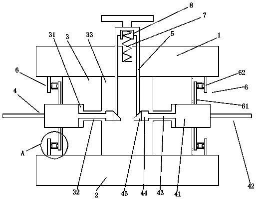
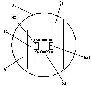
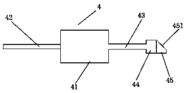
[0020] Such as Figures 1 to 4 As shown, a metal smooth driving cutting mechanism includes an upper splint 1, a lower splint 2, a connecting ring 3, a driving column 5, a cutting assembly 4, a pressing mechanism 6, a transitional elastic body 7, and a wear-resistant sleeve 8; The upper splint 1 and the lower splint 2 are respectively arranged in parallel up and down; the connecting ring 3 is installed between the upper splint 1 and the lower splint 2; the inside of the connecting ring 3 is provided with a drive cavity 33; the connecting ring 3 A plurality of telescopic slots 31 are uniformly arranged around the body; the cutting assembly 4 includes a cutting knife 42, a telescopic block 41, and a drive rod 43; a telescopic block 41 is installed radially in the telescopic slot 31 of the connecting ring 3 The outside of the telescopic block 41 i...


PUM


Abstract

The invention discloses a metal stable driving type cutting mechanism. The metal stable driving type cutting mechanism comprises an upper clamping plate, a lower clamping plate, a connecting ring, a driving column, a cutting assembly, an abutting mechanism, a transitional elastic body and a wear-resistant sleeve. The transition elastic body is added between the upper end of the driving column andthe upper clamping plate, the wear-resistant sleeve sleeves the upper end of the transition elastic body, thus, the driving column is stable during rotary stretching and retracting, and friction is avoided.

Description

technical field [0001] The invention relates to a metal smooth driving cutting mechanism. Background technique [0002] At present, metal plates or blocks sometimes need to be cut. The existing ones need to be cut with a cutting knife, but the existing cutting is all fixed on the knife seat, and the cutting knife cannot be carried out on the knife seat. Floating and telescopic, different processing conditions may require different cutting depths. If the cutting knife cannot be floating and socketed, the range of use and flexibility will be greatly limited. The present invention needs to provide a metal cutting mechanism that can be stretched and floated. Contents of the invention [0003] Aiming at the deficiencies of the above-mentioned prior art, the problem to be solved by the present invention is: to provide a metal cutting mechanism with stable driving and telescopic floating. [0004] In order to solve the above problems, the technical scheme that the present invent...

Claims


Application Information

Patent Timeline
Patent Type & Authority Applications(China)
IPC IPC(8): B23D79/00B23Q3/00
CPCB23D79/00B23Q3/00
Inventor 孙颖
Owner 江苏云佳金属制品有限公司
Why Eureka
Try Eureka