Cable trench
A cable trench and cable support technology, applied in cable installation, ground cable installation, electrical components, etc., can solve the problems of high cost and complicated design process, and achieve the effect of obvious effect and low investment cost.
- Summary
- Abstract
- Description
- Claims
- Application Information
AI Technical Summary
Problems solved by technology
Method used
Image
Examples
Embodiment 1
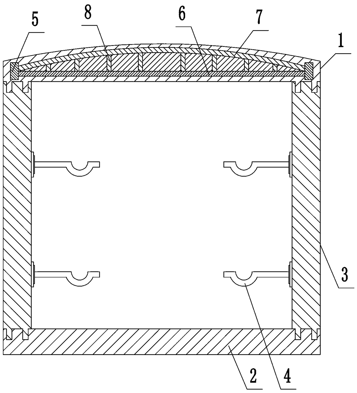
[0033] like figure 1 As shown, the present invention discloses a cable trench, which includes a trench body and a cover plate 1 arranged on the upper end of the trench body. The cable support 4 is arranged on the top, and the cable support 4 adopts the structure in the prior art to be arranged in rows;
[0034] The cover plate 1 is a reinforced concrete structure, the upper end surface of the cover plate 1 is an arc-shaped structure, and a support frame is arranged inside the cover plate. The support frame includes an outer frame 5 and a plurality of arch supports arranged in the outer frame 5, and the arch supports are equally spaced. Arranged in rows; the arch support includes a lower support rod 6 fixedly connected to the outer frame, an upper support rod 7 fixed at both ends of the lower support rod 6, a plurality of vertical rods between the lower support rod 6 and the upper support rod 7 8. The upper support rod 7 is an arc-shaped structure. In specific use, anti-slip ...
Embodiment 2
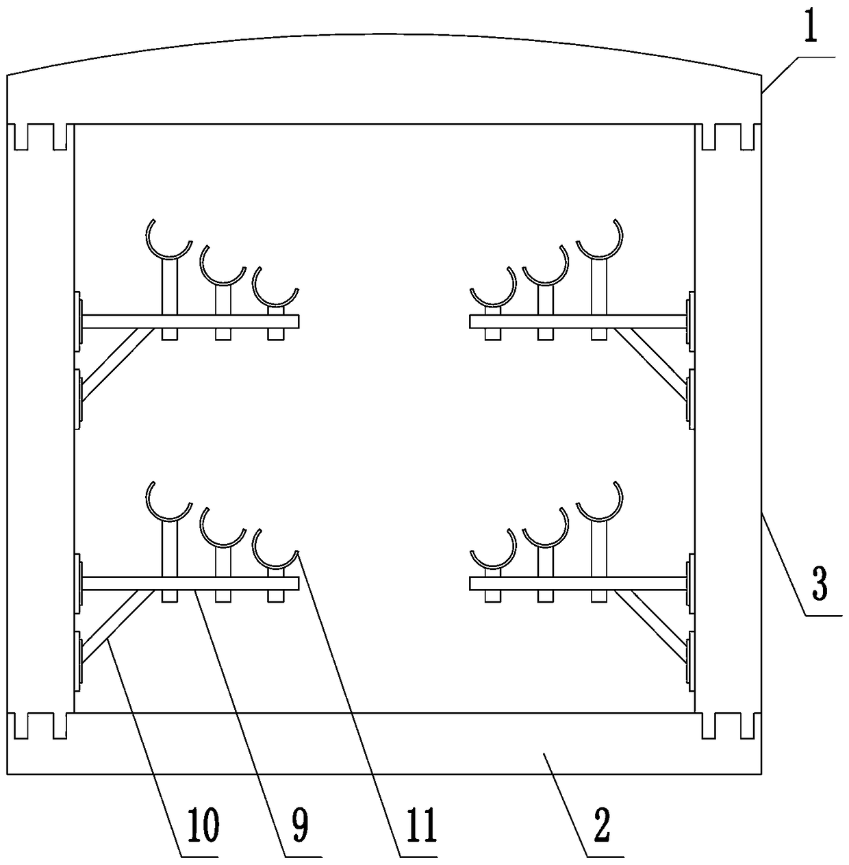
[0040] combine figure 1 and figure 2 As shown, the present invention discloses a cable trench, which includes a trench body and a cover plate 1 arranged on the upper end of the trench body. Cable brackets are arranged on the top, and the cable brackets adopt a rotatable structure and are arranged in rows;
[0041]The cover plate 1 is a reinforced concrete structure, the upper end surface of the cover plate 1 is an arc-shaped structure, and a support frame is arranged inside the cover plate. The support frame includes an outer frame 5 and a plurality of arch supports arranged in the outer frame 5, and the arch supports are equally spaced. Arranged in rows; the arch support includes a lower support rod 6 fixedly connected to the outer frame, an upper support rod 7 fixed at both ends of the lower support rod 6, a plurality of vertical rods between the lower support rod 6 and the upper support rod 7 8. The upper support rod 7 is an arc-shaped structure.
[0042] The structure ...
Embodiment 3
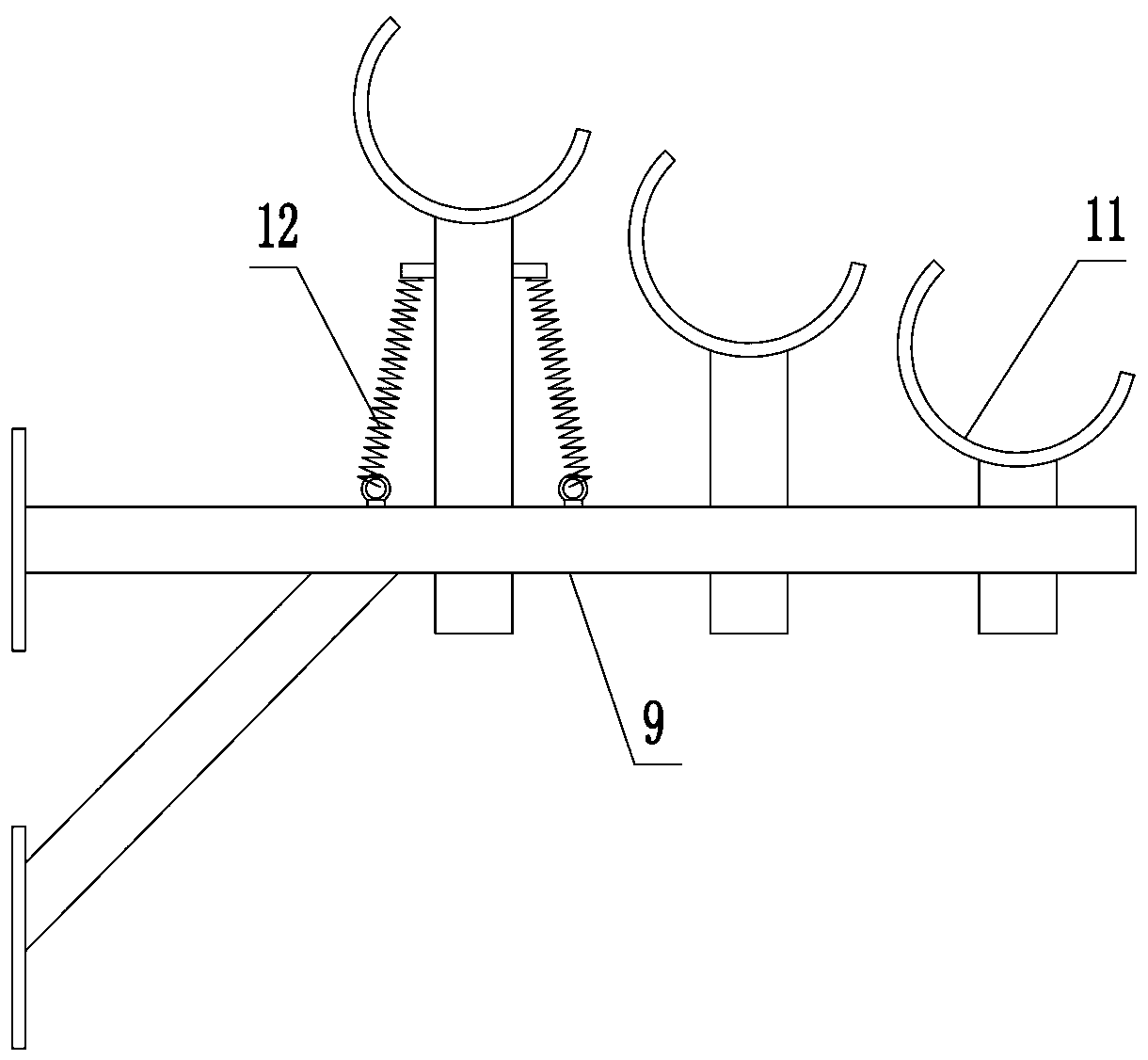
[0045] The structure of this embodiment is basically the same as that of Embodiment 2, the difference is: as image 3 As shown, the structure of the cable support is limited, two extension springs 12 are mounted symmetrically on the cable support seats of the three cable support seats 11 on the same cross bar 9 , and the lower ends of the extension springs 12 are articulated with the cross bar 9 . During the cable laying process of this structure, the two tension springs 12 arranged symmetrically can prevent the free rotation of the cable support base 11 and improve the construction efficiency in the cable laying process.
PUM
 Abstract
Description
Claims
Application Information
 - R&D Engineer
- R&D Manager
- IP Professional
- Industry Leading Data Capabilities
- Powerful AI technology
- Patent DNA Extraction
Browse by: Latest US Patents, China's latest patents, Technical Efficacy Thesaurus, Application Domain, Technology Topic, Popular Technical Reports.
© 2024 PatSnap. All rights reserved.Legal|Privacy policy|Modern Slavery Act Transparency Statement|Sitemap|About US| Contact US: help@patsnap.com


