Eureka AIR delivers breakthrough ideas for toughest innovation challenges, trusted by R&D personnel around the world.

Autonomous shooting method of unmanned aerial vehicle based on space exploration

A shooting method, drone technology, applied to computer parts, color TV parts, TV system parts, etc., can solve the problem of not being able to see details, not being able to further explore and optimize shooting angles, and users not being able to see Face and other issues, to save time and energy, improve user experience and product attractiveness

Active Publication Date: 2019-01-18
BEIJING AIRLANGO TECH CO LTD
View PDF6 Cites 11 Cited by
  • Summary
  • Abstract
  • Description
  • Claims
  • Application Information

AI Technical Summary

Problems solved by technology

See prior art one Figure 5 It can be seen that since the images collected by the UAV in real time are only used for target recognition, the position of the target in the frame, the orientation relative to the UAV, and other compositional elements are all random. Specifically, such as Figure 5 As shown in the images on the far right of the first row and the far left of the second row, due to the flying position of the drone, although the drone recognizes the vehicle, because it cannot further explore and optimize the shooting angle, the user only Can see the basic shape of the vehicle through the image, but cannot see more details (such as license plate number, etc.)
Similarly, for person recognition, as shown on the far right side of the second row, when a person faces away from the drone, although the drone can recognize his appearance, the user cannot see the face of the person

Method used


Image

  • Autonomous shooting method of unmanned aerial vehicle based on space exploration
  • Autonomous shooting method of unmanned aerial vehicle based on space exploration
  • Autonomous shooting method of unmanned aerial vehicle based on space exploration

Examples


Embodiment Construction

[0021] Below, the implementation of the technical solution will be further described in detail in conjunction with the accompanying drawings.

[0022] Those skilled in the art can understand that although the following description involves many technical details related to the embodiments of the present invention, this is only an example for illustrating the principle of the present invention, and does not imply any limitation. The present invention can be applied to occasions other than the technical details exemplified below, as long as they do not deviate from the principle and spirit of the present invention.

[0023] In addition, in order to avoid making the description in this manual limited to redundant, in the description in this manual, some technical details that can be obtained in the existing technical documents may be omitted, simplified, modified, etc. understandable to human beings, and this does not affect the adequacy of the disclosure of this specification. ...


PUM


Abstract

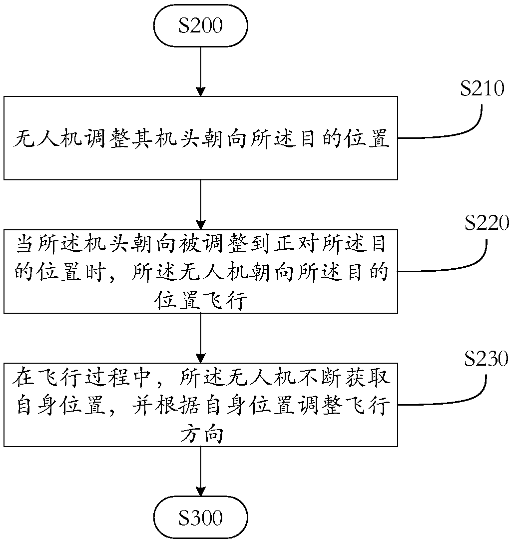
The invention relates to an autonomous shooting method of an unmanned aerial vehicle based on space exploration, which comprises the following steps: 1, setting a destination position to be explored;2, the unmanned aerial vehicle (UAV) flies from the current position to the destination position, and continuously shoots the current picture during the flight; 3, extracting picture features from that current picture, inputting the picture features to a target recognition model, and outputting the type of the target recognized in the current picture by the target recognition model; 4, if the recognized target type belongs to the preset target type, the UAV adjusts its current position and shooting angle, and shoots the target; 5, if the unmanned aerial vehicle has not reach the destination position, returning to step 2. through the analysis of the scene and the target object in the flight process of the UAV, the user can quickly reach the optimal shooting position and take pictures, so that the time and energy required for controlling the UAV shooting can be saved, the user experience and the product attraction are greatly improved, and the user does not need to possess the skilled operation skills.

Description

technical field [0001] The present disclosure relates to the technical field of computer vision information processing, in particular to computer vision information processing and shooting control methods applied to unmanned aerial vehicles, and more specifically, to an autonomous shooting method for unmanned aerial vehicles based on space exploration and target recognition / scene recognition . Background technique [0002] In recent years, with the development of artificial intelligence and machine learning algorithms, cameras are equipped with intelligent scene recognition and intelligent camera functions. Cameras with such intelligent functions can be called intelligent camera cameras. [0003] The main function of the smart photo camera is to intelligently identify the current scene and take pictures independently according to known user needs without user operation / intervention; among them, as the basis for autonomously deciding whether to take pictures of the current sc...

Claims


Application Information

Patent Timeline
Patent Type & Authority Applications(China)
IPC IPC(8): G06K9/00H04N5/232
CPCG06V20/13H04N23/60
Inventor 毛一年刘新民张邦彦袁欣
Owner BEIJING AIRLANGO TECH CO LTD
Why Eureka
Eureka Blog
Learn More