Magnetic type lamp set

A magnetic suction, lamp group technology, applied in lighting and heating equipment, semiconductor devices of light-emitting elements, lighting devices, etc., can solve the problem of inability to meet the requirements of fitting and smoothing between lamps and walls, lack of reliability and safety in use The problem is that the lamp body cannot adjust the irradiation angle, etc., to achieve the effect of convenient and quick disassembly and assembly, convenient disassembly and assembly, and safe and reliable use.

Pending Publication Date: 2019-01-18
东莞市好又快照明电器制造有限公司
View PDF4 Cites 1 Cited by
  • Summary
  • Abstract
  • Description
  • Claims
  • Application Information

AI Technical Summary

Problems solved by technology

The common structure includes the lamp body and the lamp frame track. The commonly used installation methods for the lamp frame track on the market are embedded installation and surface-mounted installation: the existing lamps are designed to avoid light spots, the overall design thickness is relatively large, and the surface-mounted installation is direct Installing the light rail on the surface of the wall is easy to install, but it cannot meet the requirements of fitting and smoothing the lamp and the wall; while the embedded installation needs to make a groove on the wall, install the light rail into the wall, and install The process is complicated and difficult, and it will cause great damage to the wall. When there is a problem in the subsequent use process, it will be troublesome to maintain, inconvenient to disassemble, easy to damage the lamps, and expensive to repair.
[0004] At present, there are screw type, hanging type and bayonet type for the cooperation between the lamp body and the lamp frame track on the market, but the disadvantages of all are that the installation steps are relatively cumbersome, and it is easy to cause poor contact when the power is turned on. Long-term use, lack of reliability and safety; and the lamp body cannot adjust the irradiation angle, which is prone to problems such as ghosting, optical waste and optical dead angle

Method used


Image

  • Magnetic type lamp set
  • Magnetic type lamp set
  • Magnetic type lamp set

Examples


Embodiment Construction

[0020] The present invention will be described in detail below in conjunction with specific embodiments and accompanying drawings.

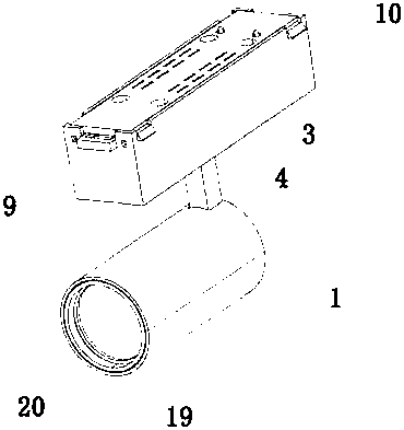
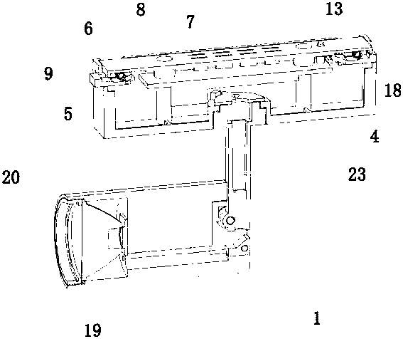
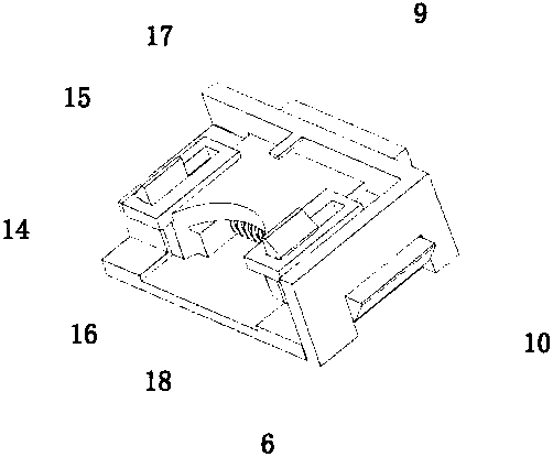
[0021] see Figure 1-6 As shown, the present invention relates to a magnetic suction lamp group, which includes a lamp body 1, a lamp frame track 2, an electrical box 3 and a hanging code 4, one end of the hanging code 4 is fixedly connected to the bottom of the electrical box 3, and the other end Rotationally connected with the lamp body 1, the electrical box 3 includes a box body 5 and a box cover 6 that are fastened and connected to each other. The inner side of the box cover 6 is connected with a magnet 7 and a drive module 8, and the two ends of the box cover 6 are connected with sliding Block press handle 9, the two sides of the slider press handle 9 are driven and connected with buckle sliders 10, the lamp holder track 2 is provided with a rail groove 11 and an iron conductor 12, and the buckle slider 10 snaps Connected in the rail groove...


PUM


Abstract

The invention discloses a magnetic type lamp set. The magnetic type lamp set comprises a lamp body, a lamp holder track, an electrical box and a cabinet hanger, wherein one end of the cabinet hanger is fixedly connected to the bottom of the electrical box, the other end of the cabinet hanger is rotationally connected with the lamp body, the electrical box comprises a box body and a box cover whichare in buckled connection, the inner side of the box cover is connected with a magnet and a driving module, the two ends of the box cover are connected with sliding block pressing handles, the two sides of the sliding block pressing handles are in driving connection with buckle sliding blocks, the lamp holder track is internally provided with a rail groove and an iron electric conductor, the buckle sliding blocks are in clamped connection in the rail groove, the driving module is welded with a power copper needle, the power copper needle penetrates through the box cover and contacts the ironelectric conductor, the power copper needle is electrically connected with the lamp body, and the magnet is attracted to the iron electric conductor. The magnetic type lamp set has the advantages thatthe installation is convenient and fast, the magnetic type lamp set is safe and reliable, and the lamplight illuminating angle can be adjusted flexibly.

Description

technical field [0001] The invention relates to the technical field of lamps, in particular to a magnetic suction lamp group. Background technique [0002] With the improvement of LED technology, LED lamps have been more and more widely used in people's daily life, and LED lamps can be divided into fixed lamps and mobile lamps: the installation of fixed lamps is mainly mechanically fixed, It is not easy to disassemble and move; mobile lamps are designed as a detachable fixed structure, which can be moved at any time to adjust the lighting area. The installation structure of such lamps is usually designed to be installed on the metal guide rail with the lamp holder and the lamp holder, and the lamp holder and the metal guide rail The wires on the lamp are electrically connected to supply power to the lamps. Because the wires are fixed and welded on the metal rail, that is, the lamp can only be installed on the position where the wires are welded on the metal rail, and it cann...

Claims


Application Information

Patent Timeline
Patent Type & Authority Applications(China)
IPC IPC(8): F21S8/00F21V21/35F21V21/14F21V17/10F21V17/16F21Y115/10
CPCF21S8/00F21V17/105F21V17/162F21V21/14F21V21/35F21Y2115/10
Inventor 黄儒成
Owner 东莞市好又快照明电器制造有限公司
Why Eureka
Try Eureka