
Flashboard lifting device used for energy storage power station

A technology for energy storage power stations and gates, which is applied in water conservancy projects, sea area projects, coastline protection, etc. It can solve the problems of inconvenient gate lifting operation, uneven force on both sides of the gate, damage to the gate or chute, etc., so as to provide work Efficiency, reduced probability of damage, simple device design

Pending Publication Date: 2019-01-18
STATE GRID CORP OF CHINA +2
View PDF1 Cites 2 Cited by
  • Summary
  • Abstract
  • Description
  • Claims
  • Application Information

AI Technical Summary

Problems solved by technology

[0002] In water conservancy projects, especially in energy storage power station projects, gates are often used to control the water storage capacity of the reservoir, but due to the limitation of the gate structure, there will be a lot of trouble in the process of lifting the gate, and the gate cannot be adjusted conveniently and efficiently. Lifting operation with limited range of adjustment
[0003] The Chinese utility model patent with the publication number CN207130696U discloses a gate lifting device for an energy storage power station, which directly uses a servo motor as power to drive the gate to lift, and there may be uneven force on both sides of the gate during use. In turn, it will cause damage to the gate or chute, and when the servo motor is working, it needs a large power

Method used


Image

  • Flashboard lifting device used for energy storage power station
  • Flashboard lifting device used for energy storage power station
  • Flashboard lifting device used for energy storage power station

Examples


Embodiment Construction

[0027] In order to make the object, technical solution and advantages of the present invention clearer, the implementation manner of the present invention will be further described in detail below in conjunction with the accompanying drawings.

[0028] It should be noted that, in the case of no conflict, the embodiments of the present invention and the features in the embodiments can be combined with each other.

[0029] In describing the present invention, it should be understood that the terms "center", "longitudinal", "transverse", "upper", "lower", "front", "rear", "left", "right", The orientations or positional relationships indicated by "vertical", "horizontal", "top", "bottom", "inner", "outer", etc. are based on the orientation or positional relationship shown in the drawings, and are only for the convenience of describing the present invention Creation and simplified description, rather than indicating or implying that the device or element referred to must have a spe...


PUM


Abstract

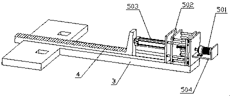
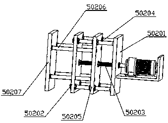
The invention discloses a flashboard lifting device used for an energy storage power station, and belongs to the technical field of energy storage power stations. In the technical scheme, the flashboard lifting device comprises a flashboard and flashboard racks on the two sides of the flashboard, the flashboard is slidingly connected with the flashboard racks, a base is arranged at the tops of theflashboard racks, fixedly connected with the flashboard racks, and provided with a lifting mechanism, one end of the lifting mechanism is connected with the flashboard, the flashboard is driven by the lifting mechanism to ascend and descend, the other end of the lifting mechanism is connected with a driving mechanism, and the driving mechanism is arranged on the base. In the technical scheme, theflashboard lifting device has the advantages that the design is simple, using is convenient, when the flashboard is lifted, the two sides of the flashboard are uniformly stressed, synchronous ascending or descending is realized, it is avoided that since stress is not uniform, the two sides of the flashboard are lifted without uniformity, in this way, the probability of flashboard damage or sliding groove damage is lowered, and working efficiency is improved.

Description

technical field [0001] The invention relates to the technical field of energy storage power stations, in particular to a gate lifting device for energy storage power stations. Background technique [0002] In water conservancy projects, especially in energy storage power station projects, gates are often used to control the water storage capacity of the reservoir, but due to the limitation of the gate structure, there will be a lot of trouble in the process of lifting the gate, and the gate cannot be adjusted conveniently and efficiently. Perform lifting operations with limited adjustment range. [0003] The Chinese utility model patent with the publication number CN207130696U discloses a gate lifting device for an energy storage power station, which directly uses a servo motor as power to drive the gate to lift, and there may be uneven force on both sides of the gate during use. In turn, it will cause damage to the gate or the chute, and the servo motor needs a lot of powe...

Claims


Application Information

Patent Timeline
IPC IPC(8): E02B7/26E02B7/36
CPCE02B7/26E02B7/36
Inventor 肖仁军杨磊田翔郭庆庄广明
Owner STATE GRID CORP OF CHINA
Learn More