
Switching device for gate channel

A switch device and channel technology, applied in the direction of roads, roads, restricted traffic, etc., can solve problems such as collision with pedestrians, high precision requirements, complex structure, etc., to achieve the effect of prolonging service life, simplifying transmission structure, and ensuring smooth operation

Inactive Publication Date: 2019-01-18
SHANGHAI HUAMING INTELLIGENT TERMINAL EQUIP
View PDF1 Cites 3 Cited by
  • Summary
  • Abstract
  • Description
  • Claims
  • Application Information

AI Technical Summary

Problems solved by technology

[0003] However, because the existing three-bar type adopts a rotating method, each oblique bar needs to be rotated 120 degrees each time to allow a pedestrian to pass through, and it is very easy to swipe the card in the process of use, resulting in collision with pedestrians.
In addition, when pedestrians lead luggage and other items or pedestrians with a fatter body pass, it will cause great inconvenience and unnecessary trouble due to the blocking of the oblique rod.
However, due to the complex structure and high cost of the fan door type, it is easy to fail to operate normally due to circuit failure.
[0004] The existing side-opening type switch door does not move in a translational manner because it is opened and closed by itself, but rotates in an arc around a support shaft, and the support shaft or fulcrum needs a support fan. The weight of the door, therefore, requires a high strength of the support shaft, and at the same time, it is necessary to use a high-power motor to drive or configure a gearbox through a low-power motor to solve the problem of the support shaft or fulcrum torque and speed, as shown in the patent disclosure document As disclosed in 201320428775.X, the transmission structure is complicated, the control precision is high, and the cost is high.

Method used


Image

  • Switching device for gate channel
  • Switching device for gate channel
  • Switching device for gate channel

Examples


Embodiment 1

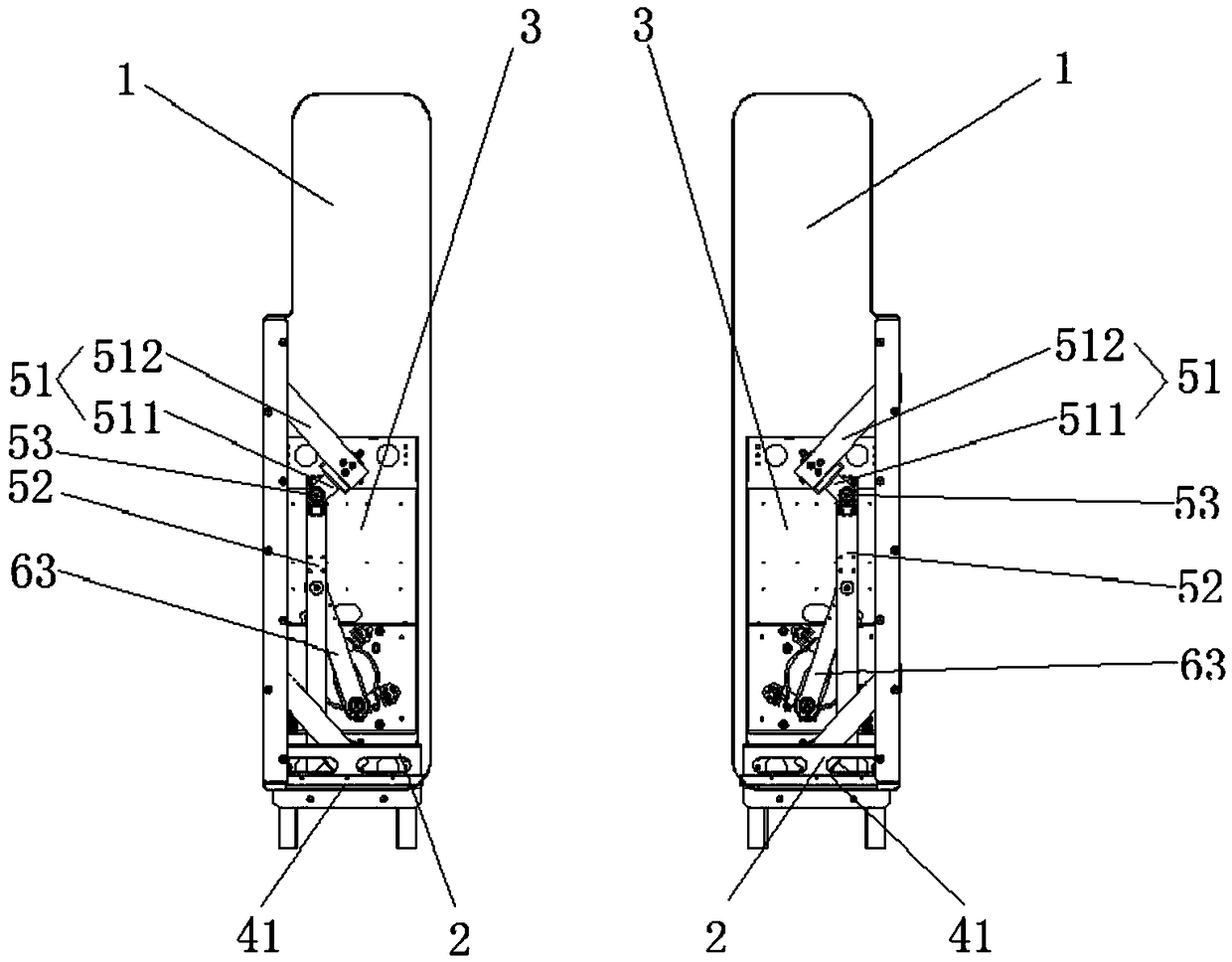
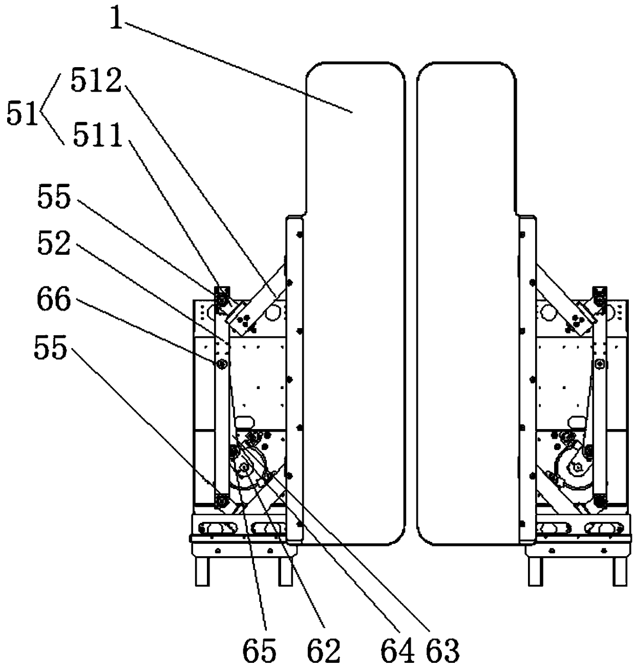
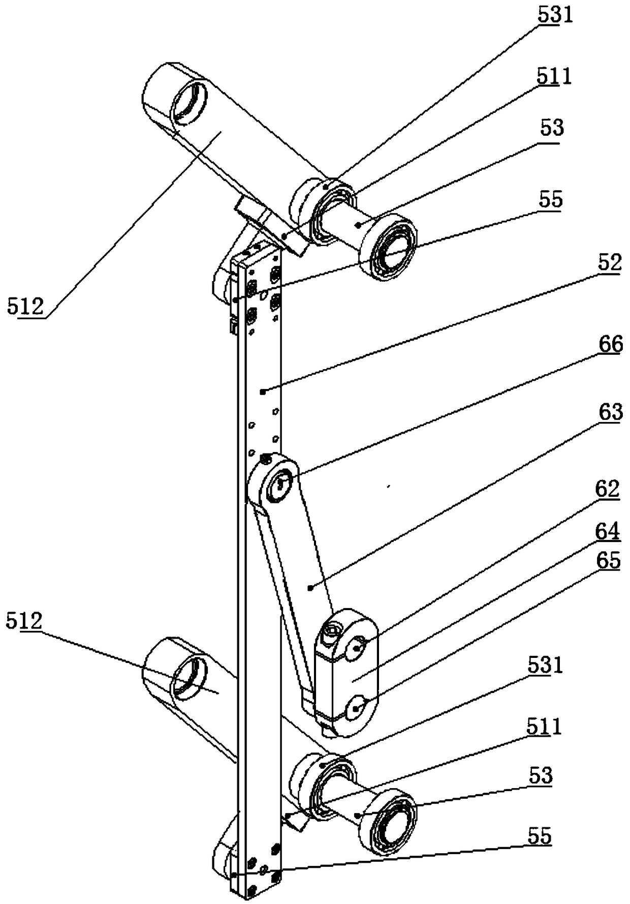
[0044] Such as figure 1 and figure 2 As shown, the first embodiment of the present invention provides a switchgear for the gate channel, including a door 1, a base 2, a frame 3, a guide rail mechanism 4 arranged on the base 2 and connected with the door 1 for movement, The connecting rod swing mechanism 5, the driving mechanism 6, etc. arranged on the frame 3 constitute.

[0045] Wherein, one end of the link swing mechanism 5 is rotationally connected with the fan door 1, and is used to make the fan door 1 reciprocate between the closing position and the door opening position of the gate channel on the guide rail mechanism 4 when the link swing mechanism 5 swings. Movement, usually, the base is set inside the gate, such as figure 1 As shown, when the door 1 is moved to the open position, most of the doors are located outside the gate. Such as figure 2 As shown, when the door 1 is moved to the closed position, most or all of the door 1 is located inside the gate.

[0046...

Embodiment 2

[0063] The second embodiment of the present invention provides a switch device for a gate channel. This embodiment is a further improvement on the above-mentioned first embodiment. The improvements are as follows: Figure 6 to Figure 7 As shown, the fan door 1 in the present embodiment is mainly composed of a door body 11, a bracket 12, a slide rail 13 arranged on the bracket 12, a slide rail 13 which is slidably arranged on the slide rail 13 and is used to rotate and connect with the connecting rod swing mechanism 5. Block 14 and so on constitute. Through the relative movement between the slider 14 and the door body 11, the door body 11 limits its upward degree of freedom under the action of its own weight, and limits its downward degree of freedom under the support of the guide rail mechanism 4 , so that when the link swing mechanism 5 is swinging, it will generate a translational thrust to the leaf door 1, and when the leaf door 1 moves on the guide rail mechanism 4, the en...

Embodiment 3

[0073] The third embodiment of the present invention provides a switch device for a gate channel. This embodiment is a further improvement to any of the above-mentioned embodiments. The improvements are as follows: Figure 8 to Figure 10 As shown, the driving mechanism 6 in this embodiment further includes: a door opening limiter 8 and a door closing limiter 9 arranged on the frame 3 . Wherein, the door 1 is in the open position when the rotating arm 64 touches the door-opening limiter 8 and stops rotating; the leaf door 1 is in the closed position when the rotating arm 64 touches the door-closing limiter 9 and stops rotating. Thereby, through the mutual cooperation of the door-opening limiter 8 and the door-closing limiter 9, the swing angle of the rotating arm 64 is limited, thereby limiting the swinging range of the swinging arm 63, and then controlling the swinging range of the connecting rod swing mechanism 5, thereby controlling the swinging range of the door 1 The trave...


PUM


Abstract

An object of the present application is to provide a switching device for a gate channel, which comprises a fan door, a base, a frame, a guide rail mechanism arranged on the base and movably connectedwith the fan door, a connecting rod swing mechanism arranged on the frame, a driving mechanism, and the like. Wherein one end of the connecting rod swing mechanism is rotatably connected with the fandoor for reciprocating movement of the fan door on the guide rail mechanism between the closed door position and the open door position of the brake passage when the connecting rod swing mechanism swings; The driving mechanism is rotatably connected with the other end of the swing link swing mechanism, and is used for driving the swing link swing mechanism to swing. In accordance with that priorart, the present application does not need to close or open the switch passage by rotating the fan door, The invention can meet the use demand of the switch control of the fan door without adopting the structure of the supporting shaft and the transmission box, simplifies the transmission structure, reduces the friction generated in the operation process of the switch device, improves the motion precision, ensures the stable operation of the swing mechanism of the connecting rod and prolongs the service life of the switch device.

Description

technical field [0001] The invention relates to a gate, in particular to a switch device for a gate channel. Background technique [0002] At present, the opening and closing doors of the existing turnstiles are usually three types: the three-bar type, the fan type and the side-opening type. [0003] However, because the existing three-bar type adopts a rotating method, each oblique bar needs to be rotated 120 degrees each time to allow a pedestrian to pass, and it is very easy to cause a collision with a pedestrian when the card is not in place during use. In addition, when pedestrians lead items such as luggage or pedestrians who are fatter to pass, great inconvenience and unnecessary trouble are caused due to the blocking of the oblique rod. However, due to the complex structure and high cost of the fan door type, it is easy to fail to operate normally due to circuit failure. [0004] The existing side-opening type switch door does not move in a translational manner bec...

Claims


Application Information

Patent Timeline
Patent Type & Authority Applications(China)
IPC IPC(8): E01F13/04
CPCE01F13/04
Inventor 张亮曾毅李海林马四龙马勇
Owner SHANGHAI HUAMING INTELLIGENT TERMINAL EQUIP
Learn More