
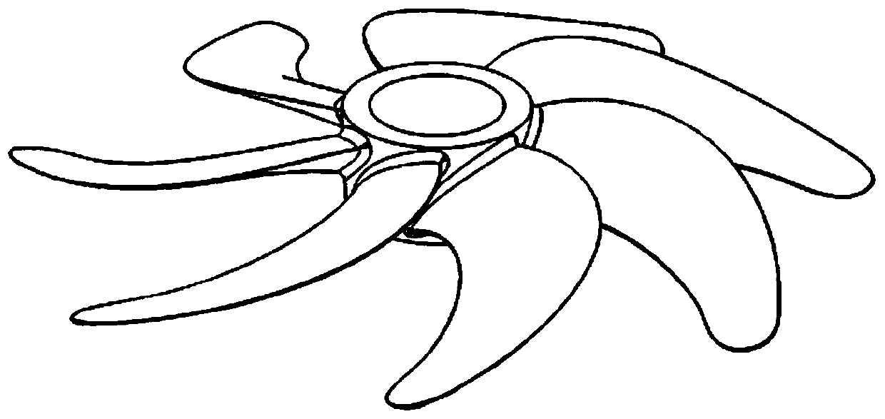
A propeller mold structure

A technology of propellers and casting molds, which is applied in the direction of casting molds, casting mold components, casting molding equipment, etc., can solve problems such as cumbersome procedures, high difficulty, and complicated operations, and achieve the effects of reducing the difficulty of molding, improving strength, and increasing thickness

Active Publication Date: 2019-09-27
DALIAN UNIV OF TECH
View PDF6 Cites 0 Cited by
  • Summary
  • Abstract
  • Description
  • Claims
  • Application Information

AI Technical Summary

Problems solved by technology

[0004] In order to overcome the problems of complex operation, cumbersome process and great difficulty in the current propeller casting molding process, the present invention proposes a new cast propeller mold structure

Method used


Image

  • A propeller mold structure
  • A propeller mold structure
  • A propeller mold structure

Examples


Embodiment Construction

[0020] The present invention will be further described below in conjunction with specific examples.

[0021] Technical scheme two of the present invention is attached figure 1 , 2 , 3, 4, including the following steps:

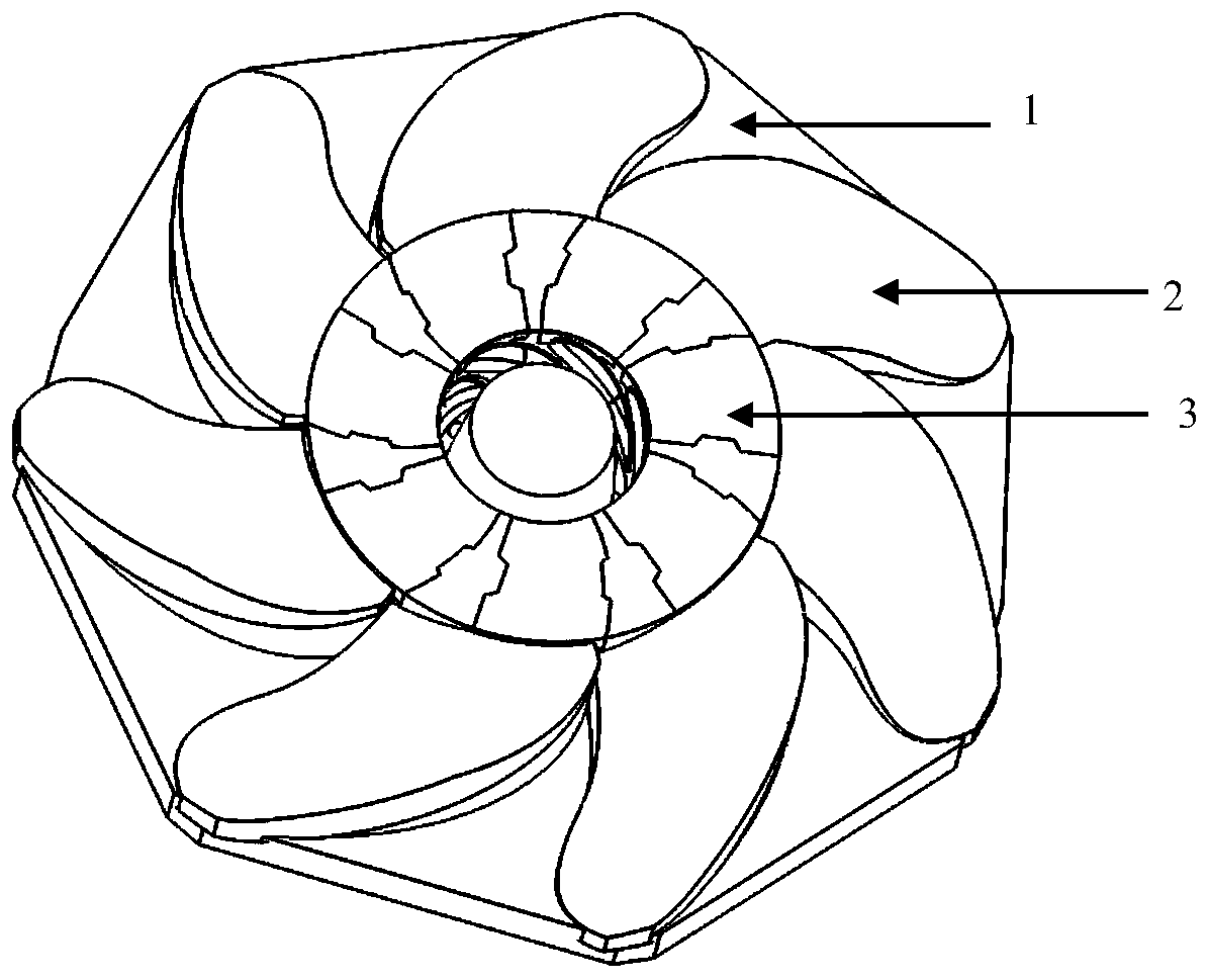
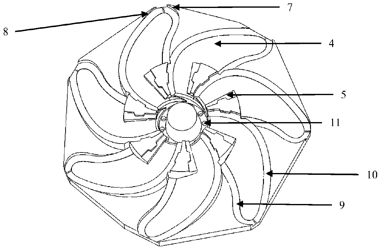
[0022] The lower form 1 includes the pressure surface 4 of the propeller mold, the positioning step 5, the part of the blade root suction surface starting from the follower, the pressure surface follower sidewall 7, the pressure surface lead sidewall 8, and the lead edge of the lower form. Profile surface 10, the edge parting surface 9 of the lower type, and the gate 11. The pressure surface 4 is arranged between the side wall 7 of the pressure surface and the side wall 8 of the pressure surface leading edge, and is located under the upper type A2 and the upper type B3 after being molded. The positioning step 5 is arranged between two adjacent upper forms B3. Part of the blade root suction surface 6 starting from the trailing edge is located below the posi...


PUM


Abstract

The invention provides a propeller molding structure and belongs to the field of molding technology. The propeller molding structure comprises an integral lower mold, upper molds A of which the numberis the same as that of blades, and upper molds B of which the number is the same as that of the blades. The external suction surfaces of the upper molds A are positioned between the leading edge parting surfaces and the following edge parting surfaces of the upper molds A, and are positioned above the pressure surfaces of the lower molds after being matched; and the leading edge parting surfacesof the upper molds A are matched with the leading edge parting surface of the lower mold after being assembled, the following edge parting surfaces of the upper molds A are matched with the followingedge parting surface of the lower mold after being assembled, and the following edge side walls of the upper molds A are perpendicular to the following edge parting surfaces and are matched with the following edge side wall of the pressure surface of the lower mold after being assembled. Partial blade root suction surfaces starting from leading edges in the upper molds B are matched with adjacentpartial blade root suction surfaces starting from following edges after being assembled so as to form internal suction surfaces; and internal leading edge parting surfaces are matched with the leadingedge parting surfaces after being assembled. The propeller molding structure provided by the invention can reduce the modeling difficulty of overlapping areas of blade roots, increase the molding thickness of propeller blade roots, enhance the molding strength of blade roots, as well as reduce the mold assembly difficulty of propeller molding.

Description

technical field [0001] The invention belongs to the field of casting technology and relates to a new propeller casting mold, which is especially suitable for casting parting of propellers with complex shapes. Background technique [0002] As a typical three-dimensional complex surface part, the propeller has a complex blade shape, and the blade shape during casting faces many insurmountable technical difficulties. [0003] The traditional spiral blade shape generally adopts the method of making a real sample wooden model or a smooth shape of a hand-made scraper. For each blade, the pressure surface and the suction surface are respectively molded, and then molded together. At the same time, the surface of the hub also needs to be Using special tooling to realize the shape, this kind of modeling method is cumbersome and the precision is not high. Contents of the invention [0004] In order to overcome the problems of complex operation, cumbersome process and great difficult...

Claims


Application Information

Patent Timeline
Patent Type & Authority Patents(China)
IPC IPC(8): B22C9/22
Inventor 姚山陈晓宇赵枢明姚平坤张雪
Owner DALIAN UNIV OF TECH
Learn More