Laser wavelength control method and device
A wavelength control and laser technology, applied in the field of lasers, can solve the problems of adjusting the wavelength center value and errors for a long time, achieve the effect of improving accuracy and efficiency, and saving debugging time
- Summary
- Abstract
- Description
- Claims
- Application Information
AI Technical Summary
Problems solved by technology
Method used
Image

Examples
Embodiment 1
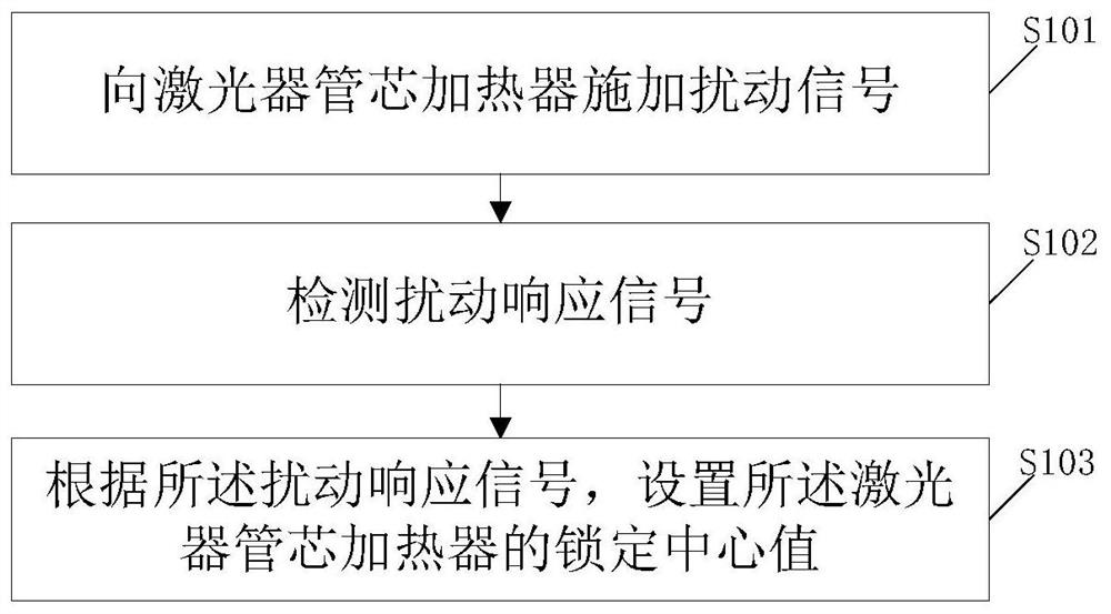
[0028] An embodiment of the present invention provides a laser wavelength control method, characterized in that the method includes:
[0029] applying a perturbation signal to the laser die heater;
[0030] Detect disturbance response signal;
[0031] According to the disturbance response signal, a locking center value of the laser die heater is set; the locking center value is used to lock the wavelength of the laser.
[0032] In the embodiment of the present invention, by applying a disturbance signal to the laser die heater; detecting the disturbance response signal; and setting the locking center value of the laser die heater according to the disturbance response signal, manual adjustment is not required, only writing The data provided by the supplier achieves the effect of automatic wavelength adjustment, saves debugging time, and thus significantly improves the wavelength locking accuracy and efficiency.
[0033] Prefixes such as "first" and "second" used in the embodi...
Embodiment 2
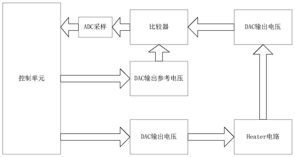
[0101] Such as figure 2 and Figure 9 As shown, a laser wavelength control device, the device includes a control unit 91 and a storage unit 92; the storage unit 92 stores a laser wavelength control computer program, and the control unit executes the computer program to achieve the following steps:
[0102] applying a perturbation signal to the laser die heater;
[0103] Detect disturbance response signal;
[0104]According to the disturbance response signal, a locking center value of the laser die heater is set; the locking center value is used to lock the wavelength of the laser.
[0105] Wherein, the control unit in the embodiment of the present invention can be FPGA, and the storage unit is a storage module built in the FPGA; of course, the control unit in the embodiment of the present invention can also be a CPU (Central Processing Unit).
[0106] In the embodiment of the present invention, by applying a disturbance signal to the laser die heater; detecting the disturb...
Embodiment 3
[0127] An embodiment of the present invention provides a computer-readable storage medium, which is characterized in that the storage medium stores a laser wavelength control computer program, and when the computer program is executed by at least one processor, any A step of said method.
[0128] The computer readable storage medium in the embodiment of the present invention may be RAM memory, flash memory, ROM memory, EPROM memory, EEPROM memory, register, hard disk, mobile hard disk, CD-ROM or any other form of storage medium known in the art. A storage medium may be coupled to the processor such that the processor can read information from, and write information to, the storage medium, or it may be an integral part of the processor. The processor and storage medium may be located in an application specific integrated circuit.
PUM
 Abstract
Description
Claims
Application Information
 - R&D
- Intellectual Property
- Life Sciences
- Materials
- Tech Scout
- Unparalleled Data Quality
- Higher Quality Content
- 60% Fewer Hallucinations
Browse by: Latest US Patents, China's latest patents, Technical Efficacy Thesaurus, Application Domain, Technology Topic, Popular Technical Reports.
© 2025 PatSnap. All rights reserved.Legal|Privacy policy|Modern Slavery Act Transparency Statement|Sitemap|About US| Contact US: help@patsnap.com