
Automotic crimping device and calibrating method for multi-position high voltage potential transformer

A technology of voltage transformer and crimping device is applied in the field of automatic crimping device and verification of multi-station high-voltage voltage transformers, which can solve the problems of difficulty in adapting to demand, high safety risk, low work efficiency, etc., and achieves an improvement in the level of automation , to ensure the effect of production safety and simple wiring

Pending Publication Date: 2019-01-15
STATE GRID CORP OF CHINA +1
View PDF0 Cites 4 Cited by
  • Summary
  • Abstract
  • Description
  • Claims
  • Application Information

AI Technical Summary

Problems solved by technology

[0005] The existing technology can detect 12 or 16 low-voltage core-through current transformers at a time, but when testing voltage transformers, only one can be detected at a time, and every time one is completed, it needs to be re-wired, and the work efficiency is low. All involve high-pressure operations, and there are certain safety risks
Disadvantages of the original technology: only one can be detected at a time, and the work efficiency is low; each wiring involves high-voltage work, and the safety risk is high; the wiring is cumbersome and complicated, and the efficiency is low
However, the traditional voltage transformer verification method has been difficult to adapt to the existing demand

Method used


Image

  • Automotic crimping device and calibrating method for multi-position high voltage potential transformer
  • Automotic crimping device and calibrating method for multi-position high voltage potential transformer
  • Automotic crimping device and calibrating method for multi-position high voltage potential transformer

Examples


Embodiment Construction

[0049] The following will clearly and completely describe the technical solutions in the embodiments of the present invention with reference to the accompanying drawings in the embodiments of the present invention. Obviously, the described embodiments are only some, not all, embodiments of the present invention. Based on the embodiments of the present invention, all other embodiments obtained by persons of ordinary skill in the art without making creative efforts belong to the protection scope of the present invention.

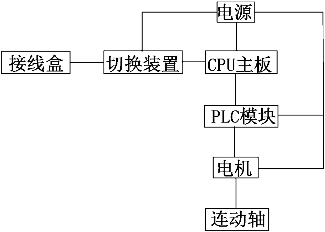
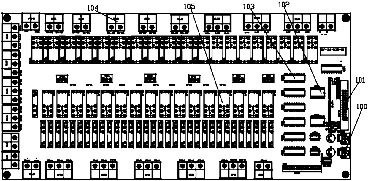
[0050] see Figure 1 to Figure 4 , the present invention provides a technical solution:

[0051] An automatic crimping device for multi-position high-voltage voltage transformers, comprising a control box 1, a linkage device 2, a high-voltage insulating rod 3, a voltage transformer under test 4, a primary A operating mechanical arm 5, a primary A crimping device 6, Standard voltage transformer 7, high-voltage primary wire 8, booster 9, secondary wiring device...


PUM


Abstract

The invention provides an automatic crimping device and a calibrating method for a multi-position high voltage potential transformer. The automatic crimping device comprises a control box, a linkage apparatus, a high-voltage insulated rod, tested potential transformers, a primary A operating robotic arm, primary A crimping devices, a standard potential transformer, a high voltage primary wire, a booster, secondary wiring apparatuses, primary X crimping devices, a secondary robotic arm, and a primary X operating robotic arm. According to the automatic crimping device and the calibrating methodfor the multi-position high voltage potential transformer, the calibrating method is combined with the crimping devices to improve the production efficiency of calibrating centers, and the daily calibrating quantity is increased from the current dozens to several hundred; the automation level of the calibrating work of the potential transformer is substantially improved, the labor intensity of workers is reduced, the wiring is simple and reliable, the work efficiency is improved, and the production safety is ensured; the automatic crimping device and the calibrating method can be directly matched with the existing transformer calibration devices of each calibrating center; and standardized, streamlined and modernized calibrating centers are conveniently established, thereby improving the working environment of the calibrating centers.

Description

technical field [0001] The invention relates to the detection field of voltage transformers, in particular to an automatic crimping device and a verification method for multi-position high-voltage voltage transformers. Background technique [0002] The voltage transformer error test can only be verified step by step. Among them, transformer calibrator, voltage load box, voltage regulator, booster and standard voltage transformer are used. After manual wiring, use manual voltage regulation or automatic voltage regulation, and then test each test point one by one according to the requirements of the regulations. [0003] It takes about 10-15 minutes to complete the verification of a voltage transformer, and each time a voltage transformer is completed, it needs to be rewired. The maximum daily inspection quantity of voltage transformers in the metrology verification department is 10 to 20 pieces. [0004] The transformer calibrator is the main instrument used to verify the ...

Claims


Application Information

Patent Timeline
Patent Type & Authority Applications(China)
IPC IPC(8): G01R35/02
CPCG01R35/02
Inventor 刘彤姜伟曾秀娟杨军柳婷婷翁炜谢慧勤孙静黄帆王晓涵
Owner STATE GRID CORP OF CHINA
Learn More