compound needle
A compound needle and needle hook technology, which is applied in the field of compound needles, can solve the problems of insufficient strength of compound needles and low strength of the needle body
- Summary
- Abstract
- Description
- Claims
- Application Information
AI Technical Summary
Problems solved by technology
Method used
Image
Examples
Embodiment approach 1
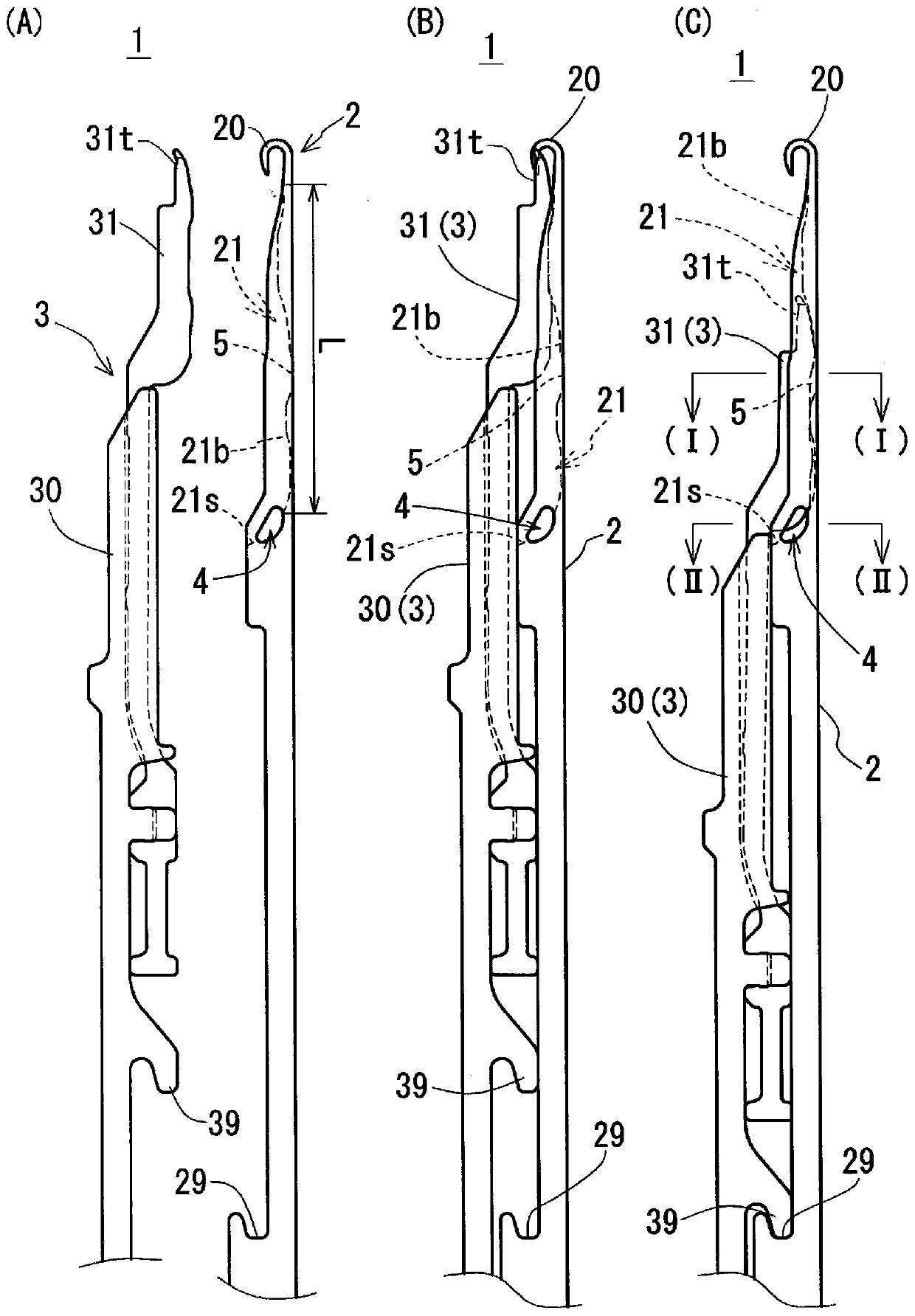
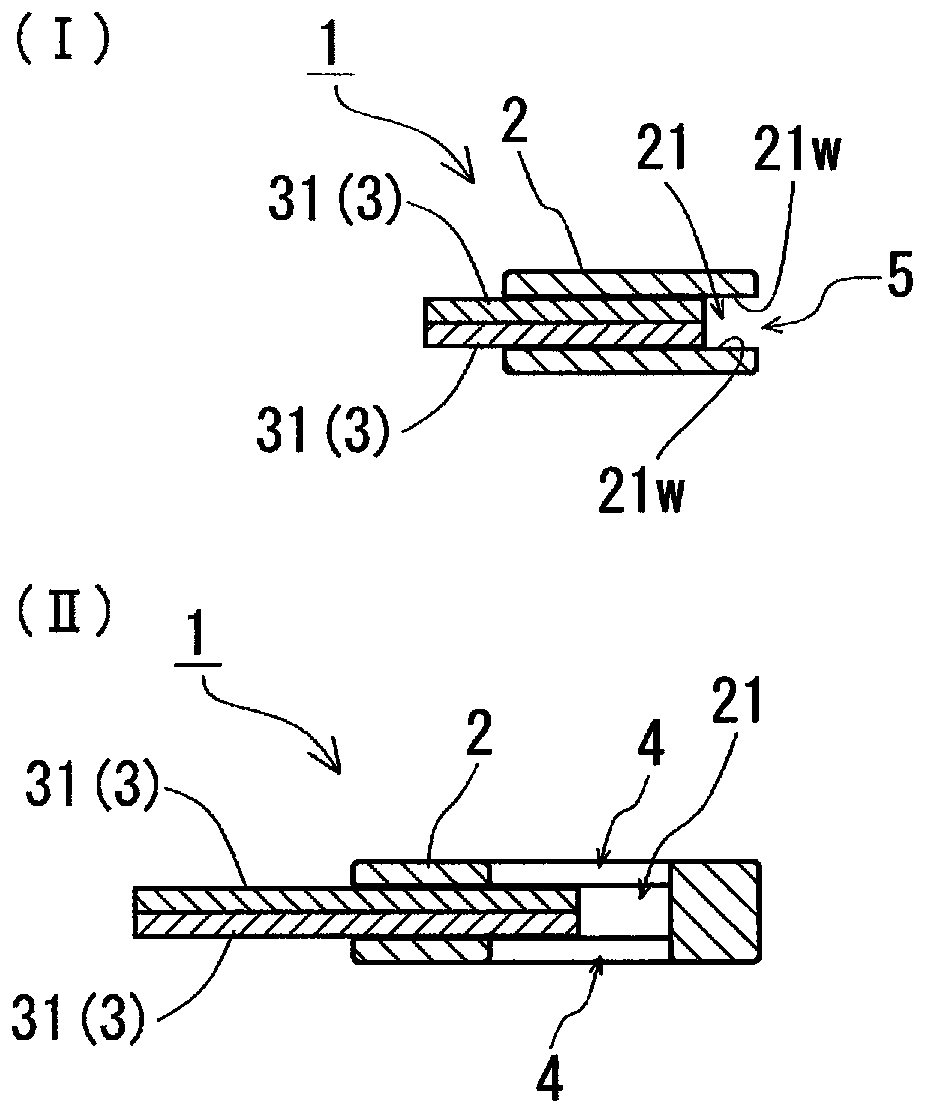
[0042] based on figure 1 , 2 The compound needle 1 according to Embodiment 1 will be described. figure 1 The top and bottom of the paper are the front and rear of the composite needle 1, the right and left of the paper are the bottom and top of the composite needle 1, and the direction perpendicular to the paper is the thickness direction of the composite needle 1. in as figure 1 (C) Sectional view of figure 2 Among them, the direction perpendicular to the outward direction of the paper surface and the way vertical to the inward direction of the paper surface are the front and rear of the compound needle 1 respectively, the right and left of the paper are the bottom and top of the compound needle 1 respectively, and the upward and downward directions on the paper are the compound needle 1 the thickness direction.
[0043] Such as figure 1 As shown in (A), the composite needle 1 includes: a needle body 2 having a hook 20 ; and a slider 3 slidably combined with the needle ...
Embodiment approach 2
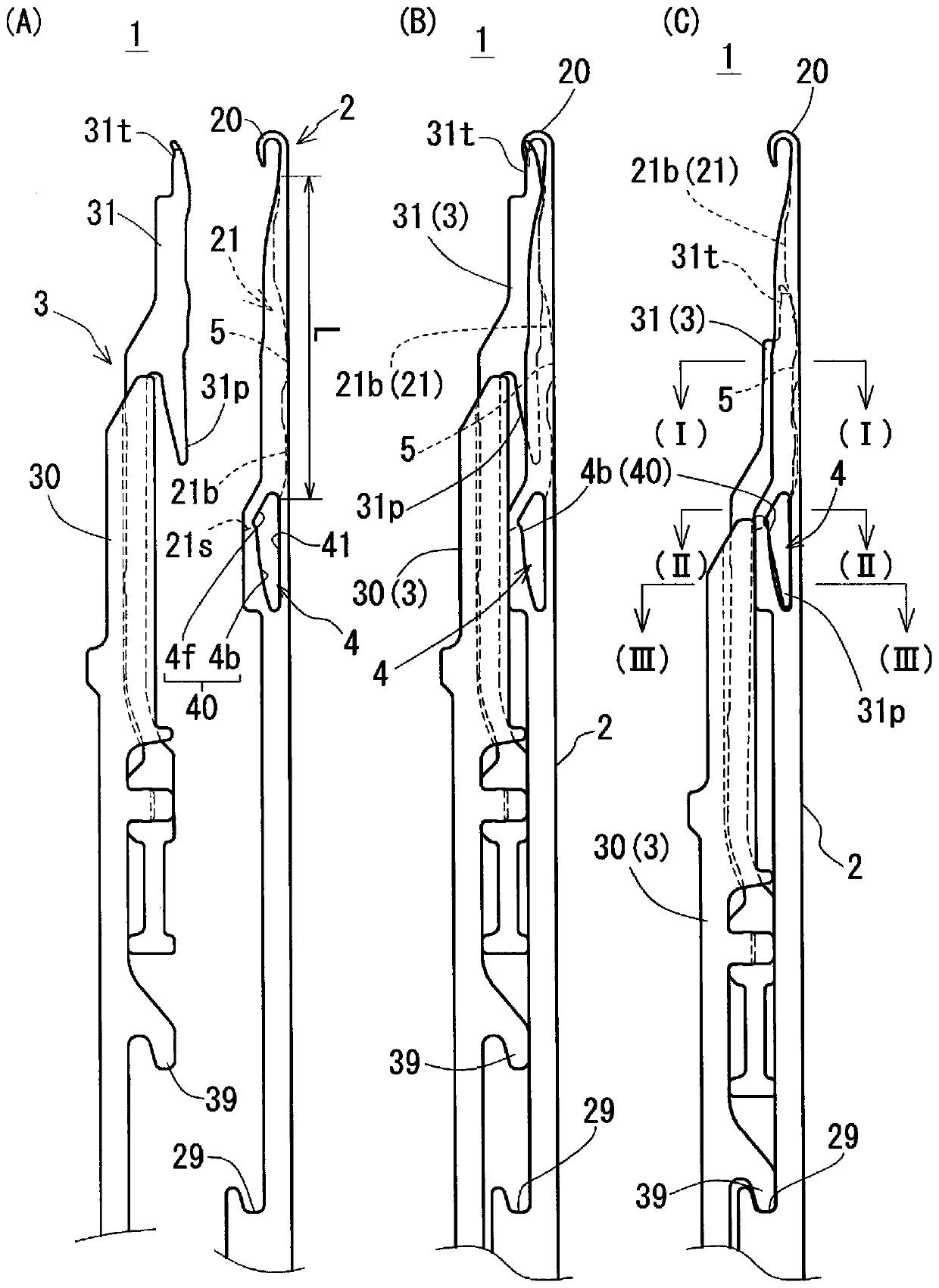
[0059] In Embodiment 2, based on image 3 , 4 A compound needle 1 having a structure different from that of the first embodiment will be described. image 3 , 4 The observation method is the same as that of Embodiment 1 figure 1 , 2 same in image 3 , 4 In , members having the same functions as those in Embodiment 1 are assigned the same reference numerals as in Embodiment 1. FIG. In the following, this embodiment will be described focusing on differences from Embodiment 1. FIG.
[0060] The main difference between the needle body 2 of this example and the needle body 2 of Embodiment 1 lies in the shape of the waste discharge window 4 included in the needle body 2 . A part of the waste discharge window 4 of this example is formed in a solid portion on the rear end side of the slider groove 21 in the sliding direction. The upper edge surface 40 and the lower edge surface 41 are formed in the solid portion of the garbage discharge window 4 . The waste discharge window 4...
PUM
 Abstract
Description
Claims
Application Information
 - R&D Engineer
- R&D Manager
- IP Professional
- Industry Leading Data Capabilities
- Powerful AI technology
- Patent DNA Extraction
Browse by: Latest US Patents, China's latest patents, Technical Efficacy Thesaurus, Application Domain, Technology Topic, Popular Technical Reports.
© 2024 PatSnap. All rights reserved.Legal|Privacy policy|Modern Slavery Act Transparency Statement|Sitemap|About US| Contact US: help@patsnap.com


