
A twin-rotor unmanned aerial vehicle with an external motor

A dual-rotor and unmanned aerial vehicle technology, applied in the directions of rotorcraft, propellers, motor vehicles, etc., can solve the problems of reducing the lift of the device, reducing the aerodynamic flow of the device, and reducing the stability of the drone.

Pending Publication Date: 2019-01-15
SHANDONG JIANZHU UNIV
View PDF0 Cites 2 Cited by
  • Summary
  • Abstract
  • Description
  • Claims
  • Application Information

AI Technical Summary

Problems solved by technology

[0002] At this stage, in the structural design of the ducted UAV, the motor, ESC, flight controller and other devices are mainly placed inside the duct, which will greatly reduce the aerodynamic flow of the entire device, reduce the lift of the entire device, and There are some ducted drones, which place the motor, ESC, flight controller and other devices on the top of the drone, which reduces the stability of the drone

Method used


Image

  • A twin-rotor unmanned aerial vehicle with an external motor
  • A twin-rotor unmanned aerial vehicle with an external motor
  • A twin-rotor unmanned aerial vehicle with an external motor

Examples


Embodiment Construction

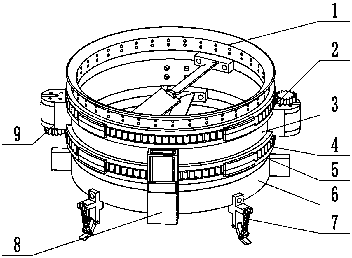
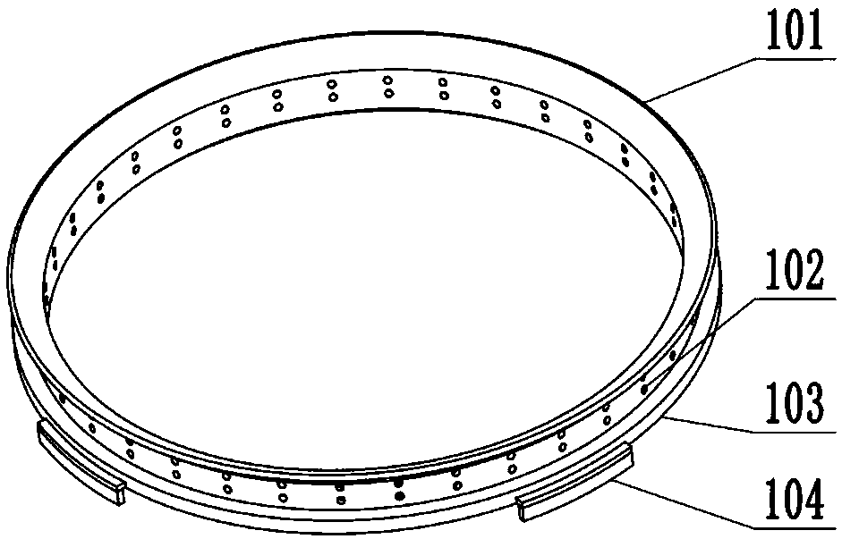
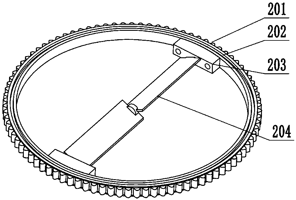
[0027] The present invention is realized through the following technical solutions: a dual-rotor unmanned aerial vehicle with an external motor, which is duct I1, upper propeller device 2, duct II3, lower propeller device 4, duct III5, chassis device 6, landing device 7 , battery device 8 and motor device 9, the lower end of the duct I1 is fixed on the upper end of the duct II3, the upper propeller device 2 is placed between the duct I1 and the duct II3, and can slide relatively, the The lower end of the duct II3 is fixed on the upper end of the duct III5, the lower propeller device 4 is placed between the duct II3 and the duct III5, and can slide relatively, and the upper end of the chassis device 6 is fixed on the lower end of the duct III5 , the landing gear 7 is distributed in a circular array at the lower end of the chassis device 6, the battery device 8 is symmetrically distributed on the duct II3 and the outer wall of the chassis unit 6, and the motor device 9 is symmetr...


PUM


Abstract

The invention relates to a twin-rotor unmanned aerial vehicle with an external motor, belonging to the field of micro unmanned aerial vehicle equipment. The twin-rotor unmanned aerial vehicle includesa duct I, an upper propeller device, a duct II, a lower propeller unit, a duct III, a chassis unit, a landing gear, a battery unit and an electric motor unit, wherein the lower end of the duct I is fixed on the upper end of the duct II, the upper propeller device is arranged between the duct I and the duct II and can slide relatively, the lower end of the duct II is fixed on the upper end of theduct III, the lower propeller device is arranged between the duct II and the duct III and can slide relatively, the upper end of the chassis device is fixed on the lower end of the duct III, the lifting and landing device is arranged in a circumferential array at the lower end of the chassis device, the battery unit is symmetrically arranged on the duct II and the outer wall of the chassis device,and the motor device is symmetrically arranged on the outer wall of the duct II, so that the twin-rotor unmanned aerial vehicle has better stability and lift force during flight.

Description

technical field [0001] The invention relates to a dual-rotor unmanned aerial vehicle with an external motor, specifically through the application of duct I, upper propeller device, duct II, lower propeller device, duct III, chassis device, landing gear, battery device and motor An unmanned aerial vehicle composed of devices belongs to the field of micro unmanned aerial vehicle equipment. Background technique [0002] At this stage, in the structural design of the ducted UAV, the motor, ESC, flight controller and other devices are mainly placed inside the duct, which will greatly reduce the aerodynamic flow of the entire device, reduce the lift of the entire device, and There are some ducted drones that place motors, ESCs, flight controllers and other devices on the top of the drone, which reduces the stability of the drone. Contents of the invention [0003] In view of the above-mentioned deficiencies, the present invention provides a dual-rotor UAV with an external motor...

Claims


Application Information

Patent Timeline
IPC IPC(8): B64C27/20B64C11/00B64C25/58
CPCB64C11/008B64C25/58B64C27/20Y02T50/60
Inventor 于复生张佳栋赵杨
Owner SHANDONG JIANZHU UNIV
Learn More